The package AixLib.Electrical.AC models alternate current electrical systems.
The package AixLib.Electrical.AC contains
component models for AC systems. The mathematics that describes AC
systems is contained in the package AixLib.Electrical.PhaseSystems.OnePhase,
in which n = 2 and m = 1. The AC models
that are part of the library can use two different assumptions.
The first assumption is that the frequency is modeled as quasi-stationary, assuming a perfect sine wave with no higher harmonics. Voltages and currents are considered as sine waves and just their amplitudes and phase shifts are taken into account during the analysis. With such an assumption, electric quantities can be represented with a phasor, i.e., a vector in the complex plane.
The second assumption is the so-called dynamic phasorial representation. The basic idea of the dynamic phasorial representation is to account for dynamic variations of the amplitude and the angle of the phasors. With such an approach, it is possible to analyze faster dynamics without directly representing all the electromagnetic effects and high-order harmonics (for more details, see Stankovic Et Al. 1999, and Stankovic A.M. and Aydin T.).
Both the quasi-stationary and the dynamic phasors represent electric quantities such as voltages and currents using phasors. The phasors are described by complex numbers that internally are represented as a vector with two components. The vectors can be represented in the so called Argand plane where on the x-axis are represented Real numbers while on the y-axis imaginary numbers.
With such a representation the complex voltages, currents, and powers are represented as
V = VRe + j VIm,
I = IRe + j IIm,
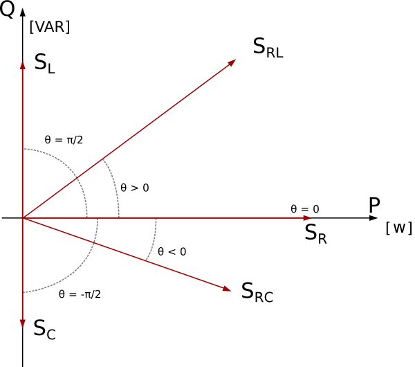
S = P + j Q,
The images below shows how the complex power vector S changes depending on the type of load.
where the subscripts indicates a
The AC connector has an additional vector that represents the
reference angle theta[PhaseSystem.m]. The reference
angle is used, for example in the AC single phase systems to
describe the phase angle of the reference voltage. This extra
information in the connector makes it overdetermined because the
number of effort variables is higher than the number of flow
variables. The over-determined connectors are defined and used in
such a way that a Modelica tool is able to remove the superfluous
but consistent equations, arriving at a balanced set of equations
based on a graph analysis of the connection structure. The models
in the library uses constructs specified by the Modelica language
to handle this situation, as described by Olsson et al. (2008).
The reference angles are usually defined by the sources (e.g.,
voltage sources or generators) and their values need to be
propagated to all the components connected to them. If more than
one generator are connected to the same network, the Modelica tool
is able to remove the superfluous equations, arriving at a balanced
set of equations based on a graph analysis of the connection
structure. The flags potentialReference and
definiteReference are used to help the Modelica tool
during the selection of the reference angle. If
definiteReference = true, then the reference angle of
the source has to be used as reference, while if
potentialReference = true, the reference angle is used
only if there are no definite sources defined.
When a model is set as definite source an icon representing a phase angle is placed close to its electrical terminal.
A.M. Stankovic,
B.C. Lesieutre, T. Aydin; Modeling and analysis of single-pahse
induction machines with dynamic phasors
IEEE Transactions on Power Systems, 14(1), Feb. 1999, pp.
9-14.
A.M. Stankovic, T.
Aydin; Analysis of asymmetrical faults in power systems using
dynamic phasors
IEEE Transactions on Power Systems, 15(3), 2000, pp.
1062-1068 .
Hans Olsson, Martin
Otter, Sven Erik Mattson and Hilding Elmqvist.
Balanced Models in Modelica 3.0 for Increased Model
Quality.
Proc. of the 7th Modelica Conference, Bielefeld, Germany, March
2008.