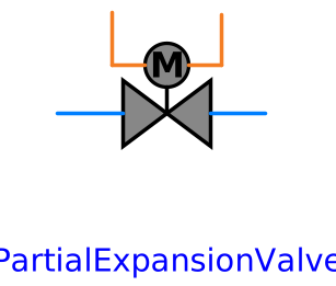
modelPartialExpansionValve
Extends from AixLib.Fluid.Interfaces.PartialTwoPortTransport (Partial element transporting fluid between two ports without storage of mass or energy).
Information
This is a base model for simple expansion valves that are used, for example, in close-loop systems like heat pumps or chillers.
Equations needed for completion
Three equations need to be added by an extending class using this component:
- The momentum balance specifying the relationship between the pressure drop dp and the mass flow rate m_flow. Therefore, different modeling approaches are suggested that can be easily expanded.
-
port_b.h_outflowfor flow in design direction. -
port_a.h_outflowfor flow in reverse direction.
Moreover, appropriate values shall be assigned to the following parameters:
-
dp_startfor a guess of the pressure drop -
m_flow_smallfor regularization of zero flow. -
dp_nominalfor nominal pressure drop. -
m_flow_nominalfor nominal mass flow rate.
Modeling approaches
Actually, three different modelling approaches are suggested and
saved as enumeration in
AixLib.Fluid.Actuators.Valves.ExpansionValves.Utilities.Choices.CalcProc.
In the following, these modeling approaches are characterised
shortly:
| Approach | Formula | Comment |
|---|---|---|
| Linear |
ṁ = C Avalve dp
|
Used for testing or initialisation |
| Nominal |
ṁ = ṁnominal / dpnominal
          Avalve dp
|
Used mainly for initialisation |
| Flow coefficient |
ṁ = C Avalve sqrt(2 ρinlet
          dp)
|
Chosen by default and follows from Bernoulli's law |
For the third approach (i.e. flow coefficient), different calculation models are stored in AixLib.Fluid.Actuators.Valves.ExpansionValves.Utilities.Choices.FlowCoefficient. Therefore, the calculation procedure of the flow coefficient C is introduced as replaceable model and must by defined by the User.
Transient behaviour
The base model has a parameter useInpFil that is
used to model the valve's transient behaviour while opening or
closing. Generally, this approach uses the same modeling attempt
as the stat-up and shut-down transients introtuced for flow
machines (see AixLib.Fluid.Movers.UsersGuide).
Therefore, just the parameter's affections are presented here:
- If
useInpFil=false, then the input signalopeSet.yis equal to the valve's opening degree. Thus, a step change in the input signal causes a step change in the opening degree. - If
useInpFil=true, which is the default, then the opening degree is equal to the output of a filter. This filter is implemented as a 2nd order differential equation. Thus, a step change in the fan input signal will cause a gradual change in the opening degree. The filter has a parameterrisTim, which by default is set to 1 second. The rise time is the time required to reach 99.6% of the full opening degree, or,if the ventil is closed, to reach a opening degree of 0.4%.
References
In the following, some general references are given for information about modelling expansion valves. The modelling approach presented here is alligned to the modelling approaches presented in the literature:
Li, W. (2013): Simplified modeling analysis ofmass flow characteristics in electronic expansion valve. In: Applied Thermal Engineering 53(1), S. 8–12
X. Cao, Z.-Y. Li, L.-L. Shao and C.-L. Zhang (2016): Refrigerant flow through electronic expansion valve: Experiment and neural network modeling. In: Applied Thermal Engineering 92, S. 210–218
Parameters
| Type | Name | Default | Description |
|---|---|---|---|
| Geometry | |||
| Modelica.Units.SI.Area | AVal | 2.5e-6 | Cross-sectional area of the valve when it is fully opened |
| Modelica.Units.SI.Diameter | dInlPip | 7.5e-3 | Diameter of the pipe at valve's inlet |
| Transient behaviour | |||
| Boolean | useInpFil | true | = true, if transient behaviour of valve opening or closing is computed |
| Modelica.Units.SI.Time | risTim | 0.5 | Time until valve opening reaches 99.6 % of its set value |
| Flow Coefficient | |||
| Utilities.Types.CalcProc | calcProc | Utilities.Types.CalcProc.nominal | Chose predefined calculation method for flow coefficient |
| Flow Coefficient › Nominal calculation | |||
| Modelica.Units.SI.MassFlowRate | mFlowNom | m_flow_nominal | Mass flow at nominal conditions |
| Modelica.Units.SI.PressureDifference | dpNom | 15e5 | Pressure drop at nominal conditions |
| Assumptions | |||
| Boolean | allowFlowReversal (from PartialTwoPort) | true | = false to simplify equations, assuming, but not enforcing, no flow reversal |
| Advanced | |||
| Modelica.Units.SI.PressureDifference | dp_start (from PartialTwoPortTransport) | 0 | Guess value of dp = port_a.p - port_b.p |
| Medium.MassFlowRate | m_flow_start (from PartialTwoPortTransport) | 0 | Guess value of m_flow = port_a.m_flow |
| Medium.MassFlowRate | m_flow_small (from PartialTwoPortTransport) | Small mass flow rate for regularization of zero flow | |
| Medium.MassFlowRate | m_flow_nominal | 0.1 | Nominal mass flow rate |
| Advanced › Diagnostics | |||
| Boolean | show_T (from PartialTwoPortTransport) | true | = true, if temperatures at port_a and port_b are computed |
| Boolean | show_V_flow (from PartialTwoPortTransport) | true | = true, if volume flow rate at inflowing port is computed |
| Boolean | show_flow_coefficient | true | = true, if flow coefficient model is computed |
| Boolean | show_staInl | true | = true, if thermodynamic state at valve's inlet is computed |
| Boolean | show_staOut | false | = true, if thermodynamic state at valve's outlet is computed |
Connectors
| Type | Name | Default | Description |
|---|---|---|---|
| Modelica.Fluid.Interfaces.FluidPort_a | port_a (from PartialTwoPort) | Fluid connector a (positive design flow direction is from port_a to port_b) | |
| Modelica.Fluid.Interfaces.FluidPort_b | port_b (from PartialTwoPort) | Fluid connector b (positive design flow direction is from port_a to port_b) | |
| Modelica.Blocks.Interfaces.RealInput | manVarVal | Prescribed expansion valve's opening | |
| Modelica.Blocks.Interfaces.RealOutput | curManVarVal | Current expansion valve's opening |
Components
| Type | Name | Default | Description |
|---|---|---|---|
| Medium.MassFlowRate | m_flow (from PartialTwoPortTransport) | Mass flow rate in design flow direction | |
| Modelica.Units.SI.PressureDifference | dp (from PartialTwoPortTransport) | Pressure difference between port_a and port_b (= port_a.p - port_b.p) | |
| Modelica.Units.SI.VolumeFlowRate | V_flow (from PartialTwoPortTransport) | m_flow/Modelica.Fluid.Utilities.regStep(m_flow, Medium.density(Medium.setState_phX(p = port_a.p, h = inStream(port_a.h_outflow), X = inStream(port_a.Xi_outflow))), Medium.density(Medium.setState_phX(p = port_b.p, h = inStream(port_b.h_outflow), X = inStream(port_b.Xi_outflow))), m_flow_small) | Volume flow rate at inflowing port (positive when flow from port_a to port_b) |
| Medium.Temperature | port_a_T (from PartialTwoPortTransport) | Modelica.Fluid.Utilities.regStep(port_a.m_flow, Medium.temperature(Medium.setState_phX(p = port_a.p, h = inStream(port_a.h_outflow), X = inStream(port_a.Xi_outflow))), Medium.temperature(Medium.setState_phX(port_a.p, port_a.h_outflow, port_a.Xi_outflow)), m_flow_small) | Temperature close to port_a, if show_T = true |
| Medium.Temperature | port_b_T (from PartialTwoPortTransport) | Modelica.Fluid.Utilities.regStep(port_b.m_flow, Medium.temperature(Medium.setState_phX(p = port_b.p, h = inStream(port_b.h_outflow), X = inStream(port_b.Xi_outflow))), Medium.temperature(Medium.setState_phX(port_b.p, port_b.h_outflow, port_b.Xi_outflow)), m_flow_small) | Temperature close to port_b, if show_T = true |
| Medium.ThermodynamicState | staInl | Thermodynamic state of the fluid at inlet condtions | |
| Medium.ThermodynamicState | staOut | Thermodynamic state of the fluid at outlet condtions | |
| FlowCoefficient | flowCoefficient | Instance of model 'flow coefficient' | |
| Real | C | Flow coefficient used to calculate mass flow and pressure drop | |
| Modelica.Blocks.Continuous.Filter | filterOpening | Second order filter to approximate valve opening or closing time | |
| Modelica.Blocks.Routing.RealPassThrough | openingThrough | Dummy passing through of opening signal to allow usage of filter |
Contents
| Name | Description |
|---|---|
 FlowCoefficient FlowCoefficient |
Revisions
- October 16, 2017, by Mirko Engelpracht, Christian Vering:
First implementation (see issue 457).