
modelStaticReset
Extends from Modelica.Icons.Example (Icon for runnable examples).
Information
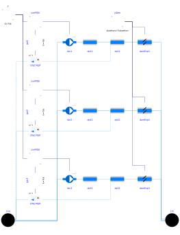
This example model compares the three power computation methods in a scenario where the fan performance (P vs. V̇) is examined to verify savings of a static pressure reset. The fan speed is controlled to track the duct static pressure at a point downstream while the damper (representing a VAV box) moves from fully closed to fully open. The system was described in Englander and Norford (1992). The fan data are implemented in AixLib.Fluid.Movers.Examples.Data.EnglanderNorford1992.
- The first fan uses the fan curve to estimate the shaft power at reduced speed.
- The second fan uses the Euler number and its correlation to estimate the hydraulic efficiency.
- The third fan assumes a constant hydraulic efficiency.
In the results, P computed from the Euler number and from the power curve agree on the trend of P vs. V̇. Both of them are also able to prevent P from incorrectly going to zero as V̇ approaches zero, which the method with constant efficiency failed.
References
Englander, S. L., and L. K. Norford. "Saving fan energy in VAV systems- part 1: analysis of a variable-speed-drive retrofit." ASHRAE Winter Meeting, Anaheim, CA, USA, 01/25-29/92. 1992.
Parameters
| Type | Name | Default | Description |
|---|---|---|---|
| Modelica.Units.SI.VolumeFlowRate | V_flow_nominal | 21.8 | Nominal volumetric flow rate of the system |
| Modelica.Units.SI.MassFlowRate | m_flow_nominal | V_flow_nominal/1.2 | Nominal mass flow rate of the system |
| Modelica.Units.SI.PressureDifference | dp_nominal | 1244.2 | Nominal pressure rise of the system |
Components
| Type | Name | Default | Description |
|---|---|---|---|
| AixLib.Fluid.Movers.SpeedControlled_y | fan1 | Fan using power curves | |
| AixLib.Fluid.Movers.SpeedControlled_y | fan2 | Fan using the Euler number | |
| AixLib.Fluid.Movers.SpeedControlled_y | fan3 | Fan using constant efficiency | |
| AixLib.Fluid.Sources.Boundary_pT | sou | Boundary | |
| AixLib.Fluid.Sources.Boundary_pT | sin | Boundary | |
| AixLib.Fluid.FixedResistances.PressureDrop | dp11 | Duct pressure drop before the static pressure measurement point | |
| AixLib.Fluid.FixedResistances.PressureDrop | dp12 | Duct pressure drop after the static pressure measurement point | |
| AixLib.Fluid.FixedResistances.PressureDrop | dp21 | Duct pressure drop before the static pressure measurement point | |
| AixLib.Fluid.FixedResistances.PressureDrop | dp22 | Duct pressure drop after the static pressure measurement point | |
| AixLib.Fluid.FixedResistances.PressureDrop | dp31 | Duct pressure drop before the static pressure measurement point | |
| AixLib.Fluid.FixedResistances.PressureDrop | dp32 | Duct pressure drop after the static pressure measurement point | |
| AixLib.Fluid.Sensors.RelativePressure | pDucSta1 | Duct static pressure | |
| AixLib.Fluid.Sensors.RelativePressure | pDucSta2 | Duct static pressure | |
| AixLib.Fluid.Sensors.RelativePressure | pDucSta3 | Duct static pressure | |
| AixLib.Controls.Continuous.LimPID | conPID1 | PI controller | |
| AixLib.Controls.Continuous.LimPID | conPID2 | PI controller | |
| AixLib.Controls.Continuous.LimPID | conPID3 | PI controller | |
| Modelica.Blocks.Math.Gain | gai1 | Gain | |
| Modelica.Blocks.Math.Gain | gai2 | Gain | |
| Modelica.Blocks.Math.Gain | gai3 | Gain | |
| Modelica.Blocks.Sources.Constant | y | Duct static pressure setpoint (normalised) | |
| Actuators.Dampers.Exponential | damExp1 | Damper representing a VAV box | |
| Actuators.Dampers.Exponential | damExp2 | Damper representing a VAV box | |
| Actuators.Dampers.Exponential | damExp3 | Damper representing a VAV box | |
| Modelica.Blocks.Sources.Ramp | yDam | Ramp input for damper position |
Contents
| Name | Description |
|---|---|
 Medium Medium |
Revisions
-
January 24, 2022, by Hongxiang Fu and David Blum:
First implementation. This is for #2668.