modelCycleHP
Extends from AixLib.Obsolete.BaseClasses.ObsoleteModel (Icon for classes that are obsolete and will be removed in later versions).
Information
Overview
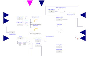
Heat pump refrigerant circuit black box model, no controllers included. It is used within the HeatPump model and delivers the basic functionality of the heat pump. The HeatPump model only adds the external heat exchangers and according connectors.
Assumptions
Correction models of the calculation can be activated that effect the efficiency or the start-up and shut-off behavior of the heat pump.
- Icing and Defrosting: Simple model that uses the evaporator inlet temperature and calculates a factor for CoP correction (according to Wetter and Afjei, 1996). Not enabled for table data, as usually already included (data according EN255 and EN14511).
- Mass flow in condenser/evaporator: Model according to Pahud and Lachal, 2004, that corrects the temperatures used within table and polynomial. If the mass flow rates are already taken into account in the chosen polynomial, this sould be deactivated!
- First order behavior of heat pump capacity: Start-up and shut-off of heat pump can be modeled with a first order behavior.
- Electric efficiency: The electric efficiency of the electric drive is implemented to calculate the evaporator heat flow
- Scaling factor: A scaling facor is implemented for scaling of the heat pump power and capacity without effecting the heat pump efficiency which is not physically correct but may be helpful for rough calculation.
- Additional electric power: This is a constant value that is added to the power consumption. This may be helpful if e.g. an electric drive operates together with the compressor and shall be included in overall electric power and CoP calculation.
- The smoothness of table interpolation can be chosen.
- Allowed sink temperature: A maximum condenser outlet temperature limits the condenser heat flow through a PID controller.
Known Limitations
- Allowed source temperature: No limits for source temperature is implemented. Though, usually this is not a problem if the heat pump is properly integrated into a system model.
Concept
Works as on/off-controlled heat pump or heat pump with capacity control. The type of capacity and electrical power calculation can be chosen:
- Polynom
a) depending on evaporator input temperature, condenser output temperature and variable speed (via conditional speed connector) for capacity controlled heat pumps
b) depending on evaporator input temperature, condenser output temperature and nominal speed for on/off-controlled heat pump - Table data according for on/off-controlled heat pump, depending on evaporator input temperature, condenser output temperature
The heat pump speed is helt between the boundaries N_min and N_max even if the input speed is higher or lower. But no further controlling is implemented! The control logic is conciously not integrated into this model!
The calculation of the capacity and electric power does not represent any dynamic behavior of the refrigerant cycle as it occurs in real heat pumps. Therefore two possibilities exist, to add dynamic behavior:
- The condenser and evaporator can be parametized with a certain external fluid volume to represent their thermal inertia in the tab Evaporator/Condenser
- A first order element can be added to the calculation in the tab Advanced if the check box PT1_cycle is enabled (see: Correction models)
References
Sources:
- Pahud, D. and Lachal, B.: Mesure des performances thermiques d?une pompe à chaleur couplée sur des sondes géothermiques à Lugano (TI). Office fédéral de l'energie, Bern, Switzerland. 2004.
- Wetter, M. and Afjei, T.: TRNSYS TYPE 401 - Kompressionswärmepumpe inklusiv Frost- und Taktverluste. Zentralschweizerisches Technikum Luzern - Ingenieruschule HTL, Switzerland. 1996.
Parameters
| Type | Name | Default | Description |
|---|---|---|---|
| Heat Pump cycle | |||
| Boolean | HPctrlType | true | Capacity control type |
| Integer | capCalcType | 1 | Type of capacity calculation |
| SI.Temperature | T_conMax | 338.15 | Maximum condenser outlet temperature |
| Capacity data | |||
| DataBase.HeatPump.HeatPumpBaseDataDefinition | dataTable | AixLib.Obsolete.Year2024.DataBase.HeatPump.EN255.Vitocal350BWH113() | Look-up table data for on/off heat pump according to EN255/EN14511 |
| Real | N_max | 4200 | Maximum speed of compressor in 1/min (only used if used in polynom) |
| Real | N_min | 1500 | Minimum speed of compressor in 1/min (only used if used in polynom) |
| Real | N_nom | 3600 | Nominal speed of compressor in 1/min (only used if used in polynom) |
| Advanced › Start/stop behavior | |||
| Boolean | PT1_cycle | false | First Order model for capacity |
| SI.Time | timeConstantCycle | 1 | Time constant for first order model |
| Advanced › Assumptions | |||
| Real | eta_ele | 1 | Assumption of P_tech/P_el (for calculation of Evaporator load) |
| Real | factorScale | 1 | Scaling factor (Attention: not physically correct) |
| SI.Power | P_eleAdd | 0 | Additional electric power when heat pump is on (not influenced through scaling factor) |
| Modelica.Blocks.Types.Smoothness | smoothness | Modelica.Blocks.Types.Smoothness.LinearSegments | Smoothness of table interpolation |
| Advanced › Mass flow correction | |||
| Boolean | CorrFlowCo | false | Correction of mass flow different from nominal flow in condenser (use only if not included in polynom) |
| SI.MassFlowRate | mFlow_conNominal | 0.5 | Nominal mass flow rate in condenser |
| Boolean | CorrFlowEv | false | Correction of mass flow different from nominal flow in evaporator (use only if not included in polynom) |
| SI.MassFlowRate | mFlow_evaNominal | 0.5 | Nominal mass flow rate in evaporator |
Connectors
| Type | Name | Default | Description |
|---|---|---|---|
| Modelica.Blocks.Interfaces.RealOutput | P_eleOut | ||
| Modelica.Blocks.Interfaces.BooleanInput | onOff_in | ||
| Modelica.Blocks.Interfaces.RealOutput | CoP_out | ||
| Modelica.Blocks.Interfaces.RealInput | N_in | ||
| Modelica.Blocks.Interfaces.RealOutput | Qdot_conOut | Value of Real output | |
| Modelica.Blocks.Interfaces.RealInput | T_conIn | Connector of Real input signal to be converted | |
| Modelica.Blocks.Interfaces.RealInput | T_evaIn | Connector of Real input signal to be converted | |
| Modelica.Blocks.Interfaces.RealOutput | Qdot_evaOut | Value of Real output | |
| Modelica.Blocks.Interfaces.RealInput | T_conOut | Connector of Real input signal to be converted | |
| Modelica.Blocks.Interfaces.RealInput | T_evaOut | Connector of Real input signal to be converted | |
| Modelica.Blocks.Interfaces.RealInput | mFlow_eva | Connector of Real input signal to be converted | |
| Modelica.Blocks.Interfaces.RealInput | mFlow_con | Connector of Real input signal to be converted |
Components
Contents
| Name | Description |
|---|---|
 data_poly data_poly | |
 Corr_icing Corr_icing |
Revisions
-
March 27, 2013 by Kristian Huchtemann:
Added maximum condenser temperature implementation. -
December 10, 2013 by Ole Odendahl:
Formatted documentation appropriately -
April 23, 2013 by Kristian Huchtemann:
implemented