modelPartialReversibleVapourCompressionMachine
Extends from AixLib.Fluid.Interfaces.PartialFourPortInterface (Partial model with four ports and declaration of quantities that are used by many models).
Information
This partial model for a generic grey-box vapour compression machine (heat pump or chiller) uses empirical data to model the refrigerant cycle. The modelling of system inertias and heat losses allow the simulation of transient states.
Resulting in the choosen model structure, several configurations are possible:
- Compressor type: on/off or inverter controlled
- Reversible operation / only main operation
- Source/Sink: Any combination of mediums is possible
- Generik: Losses and inertias can be switched on or off.
Concept
Using a signal bus as a connector, this model working as a heat pump can be easily combined with several control or safety blocks from AixLib.Controls.HeatPump. The relevant data is aggregated. In order to control both chillers and heat pumps, both flow and return temperature are aggregated. The mode signal chooses the operation type of the vapour compression machine:
- mode = true: Main operation mode (heat pump: heating; chiller: cooling)
- mode = false: Reversible operation mode (heat pump: cooling; chiller: heating)
To model both on/off and inverter controlled vapour compression machines, the compressor speed is normalizd to a relative value between 0 and 1.
Possible icing of the evaporator is modelled with an input value between 0 and 1.
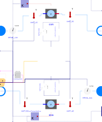
The model structure is as follows. To understand each submodel, please have a look at the corresponding model information:
- InnerCycle (Black Box): Here, the user can use between several input models or just easily create his own, modular black box model. Please look at the model description for more info.
- Inertia: A n-order element is used to model system inertias (mass and thermal) of components inside the refrigerant cycle (compressor, pipes, expansion valve)
- HeatExchanger: This new model also enable modelling of thermal interias and heat losses in a heat exchanger. Please look at the model description for more info.
Parametrization
To simplify the parametrization of the evaporator and condenser volumes and nominal mass flows there exists an option of automatic estimation based on the nominal usable power of the vapour compression machine. This function uses a linear correlation of these parameters, which was established from the linear regression of more than 20 data sets of water-to-water heat pumps from different manufacturers (e.g. Carrier, Trane, Lennox) ranging from about 25kW to 1MW nominal power. The linear regressions with coefficients of determination above 91% give a good approximation of these parameters. Nevertheless, estimates for machines outside the given range should be checked for plausibility during simulation.
Assumptions
Several assumptions where made in order to model the vapour compression machine. For a detailed description see the corresponding model.
- Performance data 2D: In order to model inverter controlled machines, the compressor speed is scaled linearly
- Performance data 2D: Reduced evaporator power as a result of icing. The icing factor is multiplied with the evaporator power.
- Inertia: The default value of the n-th order element is set to 3. This follows comparisons with experimental data. Previous heat pump models are using n = 1 as a default. However, it was pointed out that a higher order element fits a real heat pump better in
- Scaling factor: A scaling facor is implemented for scaling of the thermal power and capacity. The factor scales the parameters V, m_flow_nominal, C, GIns, GOut and dp_nominal. As a result, the vapour compression machine can supply more heat with the COP staying nearly constant. However, one has to make sure that the supplied pressure difference or mass flow is also scaled with this factor, as the nominal values do not increase said mass flow.
Known Limitations
- The n-th order element has a big influence on computational time. Reducing the order or disabling it completly will decrease computational time.
- Reversing the mode: A normal 4-way-exchange valve suffers from heat losses and irreversibilities due to switching from one mode to another. Theses losses are not taken into account.
Parameters
| Type | Name | Default | Description |
|---|---|---|---|
| Boolean | use_rev | true | Is the vapour compression machine reversible? |
| Boolean | use_autoCalc | false | Enable automatic estimation of volumes and mass flows? |
| Modelica.Units.SI.Power | Q_useNominal | 0 | Nominal usable heat flow of the vapour compression machine (HP: Heating; Chiller: Cooling) |
| Real | scalingFactor | 1 | Scaling-factor of vapour compression machine |
| Assumptions | |||
| Boolean | allowFlowReversal1 (from PartialFourPort) | true | = false to simplify equations, assuming, but not enforcing, no flow reversal for medium 1 |
| Boolean | allowFlowReversal2 (from PartialFourPort) | true | = false to simplify equations, assuming, but not enforcing, no flow reversal for medium 2 |
| Nominal condition | |||
| Modelica.Units.SI.MassFlowRate | m1_flow_nominal (from PartialFourPortInterface) | Nominal mass flow rate | |
| Modelica.Units.SI.MassFlowRate | m2_flow_nominal (from PartialFourPortInterface) | Nominal mass flow rate | |
| Advanced | |||
| Medium1.MassFlowRate | m1_flow_small (from PartialFourPortInterface) | 1E-4*abs(m1_flow_nominal) | Small mass flow rate for regularization of zero flow |
| Medium2.MassFlowRate | m2_flow_small (from PartialFourPortInterface) | 1E-4*abs(m2_flow_nominal) | Small mass flow rate for regularization of zero flow |
| Advanced › Diagnostics | |||
| Boolean | show_T (from PartialFourPortInterface) | false | = true, if actual temperature at port is computed |
| Boolean | show_TPort | false | = true, if actual temperature at port is computed |
| Refrigerant inertia | |||
| Boolean | use_refIne | true | Consider the inertia of the refrigerant cycle |
| Modelica.Units.SI.Frequency | refIneFre_constant | Cut off frequency for inertia of refrigerant cycle | |
| Integer | nthOrder | 3 | Order of refrigerant cycle interia |
| Input Connectors | |||
| Boolean | useBusConnectorOnly | false | Set true to use bus connector for modeSet, nSet and iceFac input |
| Condenser › Parameters | |||
| Modelica.Units.SI.MassFlowRate | mFlow_conNominal | Manual input of the nominal mass flow rate (if not automatically calculated) | |
| Modelica.Units.SI.Volume | VCon | Manual input of the condenser volume (if not automatically calculated) | |
| Condenser › Flow resistance | |||
| Modelica.Units.SI.PressureDifference | dpCon_nominal | Pressure drop at nominal mass flow rate | |
| Real | deltaM_con | 0.1 | Fraction of nominal mass flow rate where transition to turbulent occurs |
| Condenser › Heat Losses | |||
| Boolean | use_conCap | true | If heat losses at capacitor side are considered or not |
| Modelica.Units.SI.HeatCapacity | CCon | Heat capacity of Condenser (= cp*m). If you want to neglace the dry mass of the condenser, you can set this value to zero | |
| Modelica.Units.SI.ThermalConductance | GConOut | 0 | Constant parameter for heat transfer to the ambient. Represents a sum of thermal resistances such as conductance, insulation and natural convection. If you want to simulate a condenser with additional dry mass but without external heat losses, set the value to zero |
| Modelica.Units.SI.ThermalConductance | GConIns | 0 | Constant parameter for heat transfer to heat exchangers capacity. Represents a sum of thermal resistances such as forced convection and conduction inside of the capacity |
| Evaporator › Parameters | |||
| Modelica.Units.SI.MassFlowRate | mFlow_evaNominal | Manual input of the nominal mass flow rate (if not automatically calculated) | |
| Modelica.Units.SI.Volume | VEva | Manual input of the evaporator volume (if not automatically calculated) | |
| Evaporator › Flow resistance | |||
| Modelica.Units.SI.PressureDifference | dpEva_nominal | Pressure drop at nominal mass flow rate | |
| Real | deltaM_eva | 0.1 | Fraction of nominal mass flow rate where transition to turbulent occurs |
| Evaporator › Heat Losses | |||
| Boolean | use_evaCap | true | If heat losses at capacitor side are considered or not |
| Modelica.Units.SI.HeatCapacity | CEva | Heat capacity of Evaporator (= cp*m). If you want to neglace the dry mass of the evaporator, you can set this value to zero | |
| Modelica.Units.SI.ThermalConductance | GEvaOut | 0 | Constant parameter for heat transfer to the ambient. Represents a sum of thermal resistances such as conductance, insulation and natural convection. If you want to simulate a evaporator with additional dry mass but without external heat losses, set the value to zero |
| Modelica.Units.SI.ThermalConductance | GEvaIns | 0 | Constant parameter for heat transfer to heat exchangers capacity. Represents a sum of thermal resistances such as forced convection and conduction inside of the capacity |
| Assumptions › Temperature sensors | |||
| Modelica.Units.SI.Time | tauSenT | 1 | Time constant at nominal flow rate (use tau=0 for steady-state sensor, but see user guide for potential problems) |
| Boolean | transferHeat | true | If true, temperature T converges towards TAmb when no flow |
| Modelica.Units.SI.Time | tauHeaTraEva | 1200 | Time constant for heat transfer in temperature sensors in evaporator, default 20 minutes |
| Modelica.Units.SI.Temperature | TAmbEva_nominal | 273.15 | Fixed ambient temperature for heat transfer of sensors at the evaporator side |
| Modelica.Units.SI.Time | tauHeaTraCon | 1200 | Time constant for heat transfer in temperature sensors in condenser, default 20 minutes |
| Modelica.Units.SI.Temperature | TAmbCon_nominal | 291.15 | Fixed ambient temperature for heat transfer of sensors at the condenser side |
| Assumptions › Evaporator | |||
| Boolean | allowFlowReversalEva | true | = false to simplify equations, assuming, but not enforcing, no flow reversal |
| Assumptions › Condenser | |||
| Boolean | allowFlowReversalCon | true | = false to simplify equations, assuming, but not enforcing, no flow reversal |
| Initialization › Parameters | |||
| Modelica.Blocks.Types.Init | initType | Modelica.Blocks.Types.Init.InitialState | Type of initialization (InitialState and InitialOutput are identical) |
| Initialization › Condenser | |||
| Modelica.Media.Interfaces.Types.AbsolutePressure | pCon_start | Medium_con.p_default | Start value of pressure |
| Modelica.Media.Interfaces.Types.Temperature | TCon_start | Medium_con.T_default | Start value of temperature |
| Modelica.Units.SI.Temperature | TConCap_start | Medium_con.T_default | Initial temperature of heat capacity of condenser |
| Modelica.Media.Interfaces.Types.MassFraction[Medium_con.nX] | XCon_start | Medium_con.X_default | Start value of mass fractions m_i/m |
| Initialization › Evaporator | |||
| Modelica.Media.Interfaces.Types.AbsolutePressure | pEva_start | Medium_eva.p_default | Start value of pressure |
| Modelica.Media.Interfaces.Types.Temperature | TEva_start | Medium_eva.T_default | Start value of temperature |
| Modelica.Units.SI.Temperature | TEvaCap_start | Medium_eva.T_default | Initial temperature of heat capacity at evaporator |
| Modelica.Media.Interfaces.Types.MassFraction[Medium_eva.nX] | XEva_start | Medium_eva.X_default | Start value of mass fractions m_i/m |
| Initialization › Refrigerant inertia | |||
| Real[nthOrder] | x_start | zeros(nthOrder) | Initial or guess values of states |
| Real | yRefIne_start | 0 | Initial or guess value of output (= state) |
| Dynamics › Equation | |||
| Modelica.Fluid.Types.Dynamics | massDynamics | Modelica.Fluid.Types.Dynamics.DynamicFreeInitial | Type of mass balance: dynamic (3 initialization options) or steady state (only affects fluid-models) |
| Modelica.Fluid.Types.Dynamics | energyDynamics | Modelica.Fluid.Types.Dynamics.DynamicFreeInitial | Type of energy balance: dynamic (3 initialization options) or steady state (only affects fluid-models) |
| Advanced › General machine information | |||
| Boolean | machineType | =true if heat pump; =false if chiller | |
| Advanced › Flow resistance | |||
| Boolean | from_dp | false | = true, use m_flow = f(dp) else dp = f(m_flow) |
| Boolean | homotopyInitialization | false | = true, use homotopy method |
| Boolean | linearized | false | = true, use linear relation between m_flow and dp for any flow rate |
Connectors
| Type | Name | Default | Description |
|---|---|---|---|
| Modelica.Fluid.Interfaces.FluidPort_a | port_a1 (from PartialFourPort) | Fluid connector a1 (positive design flow direction is from port_a1 to port_b1) | |
| Modelica.Fluid.Interfaces.FluidPort_b | port_b1 (from PartialFourPort) | Fluid connector b1 (positive design flow direction is from port_a1 to port_b1) | |
| Modelica.Fluid.Interfaces.FluidPort_a | port_a2 (from PartialFourPort) | Fluid connector a2 (positive design flow direction is from port_a2 to port_b2) | |
| Modelica.Fluid.Interfaces.FluidPort_b | port_b2 (from PartialFourPort) | Fluid connector b2 (positive design flow direction is from port_a2 to port_b2) | |
| Modelica.Blocks.Interfaces.RealInput | iceFac_in | Input signal for icing factor | |
| Modelica.Blocks.Interfaces.RealInput | nSet | Input signal speed for compressor relative between 0 and 1 | |
| AixLib.Obsolete.Year2024.Controls.Interfaces.VapourCompressionMachineControlBus | sigBus | ||
| Modelica.Blocks.Interfaces.RealInput | T_amb_eva | Ambient temperature on the evaporator side | |
| Modelica.Blocks.Interfaces.RealInput | T_amb_con | Ambient temperature on the condenser side | |
| Modelica.Blocks.Interfaces.BooleanInput | modeSet | Set value of operation mode |
Components
| Type | Name | Default | Description |
|---|---|---|---|
| Medium1.MassFlowRate | m1_flow (from PartialFourPortInterface) | port_a1.m_flow | Mass flow rate from port_a1 to port_b1 (m1_flow > 0 is design flow direction) |
| Modelica.Units.SI.PressureDifference | dp1 (from PartialFourPortInterface) | port_a1.p - port_b1.p | Pressure difference between port_a1 and port_b1 |
| Medium2.MassFlowRate | m2_flow (from PartialFourPortInterface) | port_a2.m_flow | Mass flow rate from port_a2 to port_b2 (m2_flow > 0 is design flow direction) |
| Modelica.Units.SI.PressureDifference | dp2 (from PartialFourPortInterface) | port_a2.p - port_b2.p | Pressure difference between port_a2 and port_b2 |
| Medium1.ThermodynamicState | sta_a1 (from PartialFourPortInterface) | if allowFlowReversal1 then Medium1.setState_phX(port_a1.p, noEvent(actualStream(port_a1.h_outflow)), noEvent(actualStream(port_a1.Xi_outflow))) else Medium1.setState_phX(port_a1.p, inStream(port_a1.h_outflow), inStream(port_a1.Xi_outflow)) | Medium properties in port_a1 |
| Medium1.ThermodynamicState | sta_b1 (from PartialFourPortInterface) | if allowFlowReversal1 then Medium1.setState_phX(port_b1.p, noEvent(actualStream(port_b1.h_outflow)), noEvent(actualStream(port_b1.Xi_outflow))) else Medium1.setState_phX(port_b1.p, port_b1.h_outflow, port_b1.Xi_outflow) | Medium properties in port_b1 |
| Medium2.ThermodynamicState | sta_a2 (from PartialFourPortInterface) | if allowFlowReversal2 then Medium2.setState_phX(port_a2.p, noEvent(actualStream(port_a2.h_outflow)), noEvent(actualStream(port_a2.Xi_outflow))) else Medium2.setState_phX(port_a2.p, inStream(port_a2.h_outflow), inStream(port_a2.Xi_outflow)) | Medium properties in port_a2 |
| Medium2.ThermodynamicState | sta_b2 (from PartialFourPortInterface) | if allowFlowReversal2 then Medium2.setState_phX(port_b2.p, noEvent(actualStream(port_b2.h_outflow)), noEvent(actualStream(port_b2.Xi_outflow))) else Medium2.setState_phX(port_b2.p, port_b2.h_outflow, port_b2.Xi_outflow) | Medium properties in port_b2 |
| AixLib.Obsolete.Year2024.Fluid.BaseClasses.PartialInnerCycle | innerCycle | ||
| AixLib.Obsolete.Year2024.Fluid.HeatExchangers.EvaporatorCondenserWithCapacity | con | Heat exchanger model for the condenser | |
| AixLib.Obsolete.Year2024.Fluid.HeatExchangers.EvaporatorCondenserWithCapacity | eva | Heat exchanger model for the evaporator | |
| Modelica.Blocks.Continuous.CriticalDamping | heatFlowIneEva | This n-th order block represents the inertia of the refrigerant cycle and delays the heat flow | |
| Modelica.Blocks.Routing.RealPassThrough | realPassThroughnSetCon | Use default nSet value | |
| Modelica.Blocks.Continuous.CriticalDamping | heatFlowIneCon | This n-th order block represents the inertia of the refrigerant cycle and delays the heat flow | |
| Modelica.Blocks.Routing.RealPassThrough | realPassThroughnSetEva | Use default nSet value | |
| Modelica.Thermal.HeatTransfer.Sources.PrescribedTemperature | varTempOutEva | Foreces heat losses according to ambient temperature | |
| Modelica.Thermal.HeatTransfer.Sources.PrescribedTemperature | varTempOutCon | Foreces heat losses according to ambient temperature | |
| AixLib.Fluid.Sensors.TemperatureTwoPort | senT_a2 | Temperature at sink inlet | |
| AixLib.Fluid.Sensors.TemperatureTwoPort | senT_b2 | Temperature at sink outlet | |
| AixLib.Fluid.Sensors.MassFlowRate | mFlow_eva | Mass flow sensor at the evaporator | |
| AixLib.Fluid.Sensors.TemperatureTwoPort | senT_b1 | Temperature at sink outlet | |
| AixLib.Fluid.Sensors.TemperatureTwoPort | senT_a1 | Temperature at sink inlet | |
| AixLib.Fluid.Sensors.MassFlowRate | mFlow_con | Mass flow sensor at the evaporator | |
| Modelica.Blocks.Logical.GreaterThreshold | greaterThreshold | Use default nSet value |
Contents
| Name | Description |
|---|---|
 Medium_con Medium_con | Medium at sink side |
| Medium_eva | Medium at source side |