
modelHVAC_DRAW_Controlled
Draw through HVAC system with control
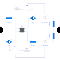
Extends from Modelica.Icons.Example (Icon for runnable examples), BaseClasses.SystemBase.
Information
This model represents a draw-through HVAC system with control. It includes components such as heat exchangers, fans, pressure drop elements, and PI controllers to regulate the mass flow rates of the supply air (SA) and exhaust air (EA).
Details
- The control system regulates the mass flow rate of supply air and exhaust air using PI controllers.
- The ducts for supply and exhaust air are modeled using fixed flow resistances.
Parameters
| Type | Name | Default | Description |
|---|---|---|---|
| Boundary Conditions | |||
| Modelica.Units.SI.Pressure | pAmb (from SystemBase) | Medium.p_default | Ambient air pressure |
| Modelica.Media.Interfaces.Types.Temperature | TIA (from SystemBase) | 297.15 | Temperature indoor air |
| Modelica.Media.Interfaces.Types.Temperature | TOA (from SystemBase) | 263.15 | Temperature outdoor air |
| Controls | |||
| Real | k | 9 | Gain of controllers |
| Modelica.Units.SI.Time | Ti | 3 | Time constants of Integrator blocks |
| Modelica.Units.SI.MassFlowRate | m_flow_set_SA | 1.0 | Set point mass flow rate SA |
| Modelica.Units.SI.MassFlowRate | m_flow_set_EA | 1.0 | Set point mass flow rate EA |
| Diagnostics | |||
| Boolean | show_T | true | = true, if actual temperature at port is computed |