This controller can be used both for DC/DC and AC/DC converters.
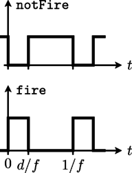
The signal input of the PWM controller is the duty cycle; the duty
cycle is the ratio of the on time to the switching period. The
output firing signal is strictly determined by the actual duty
cycle, indicated as d in Fig. 1.
 |
The firing signal is generated by comparing the sampled duty cycle input with a periodic saw tooth signal [Williams2006].