modelChillerDXHeatingEconomizer
Information
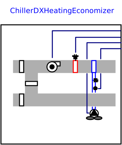
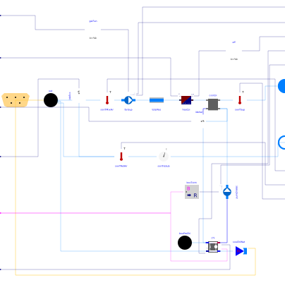
This is a conventional single zone VAV HVAC system model. The system contains a variable speed supply fan, electric heating coil, water-based cooling coil, economizer, and air-cooled chiller. The control of the system is that of conventional VAV heating and cooling. During cooling, the supply air temperature is held constant while the supply air flow is modulated from maximum to minimum according to zone load. This is done by modulating the fan speed. During heating, the supply air flow is held at a constant minimum while the heating coil is modulated accoding to zone load. The mass flow of chilled water through the cooling coil is controlled by a three-way valve to maintain the supply air temperature setpoint during cooling. The mixing box maintains the minimum outside airflow fraction unless conditions for economizer are met, in which case the economizer controller adjusts the outside airflow fraction to meet a mixed air temperature setpoint. The economizer is enabled if the outside air drybulb temperature is lower than the return air temperature and the system is not in heating mode.
There are a number of assumptions in the model. Pressure drops through the system are collected into a single component. The mass flow of return air is equal to the mass flow of supply air. The mass flow of outside air and relief air in the mixing box is ideally controlled so that the supply air is composed of the specified outside airflow fraction, rather than having feedback control of damper positions. The cooling coil is a dry coil model.
Parameters
| Type | Name | Default | Description |
|---|---|---|---|
| Modelica.Units.SI.DimensionlessRatio | COP_nominal | 5.5 | Nominal COP of the chiller |
| Modelica.Units.SI.Temperature | TSupChi_nominal | Design value for chiller leaving water temperature | |
| Modelica.Units.SI.MassFlowRate | mChiEva_flow_nominal | -QCoo_flow_nominal/Buildings.Utilities.Psychrometrics.Constants.cpWatLiq/4 | Design chilled water supply flow |
| Modelica.Units.SI.MassFlowRate | mChiCon_flow_nominal | -QCoo_flow_nominal*(1 + 1/COP_nominal)/Buildings.Utilities.Psychrometrics.Constants.cpAir/10 | Design condenser air flow |
| Air design | |||
| Modelica.Units.SI.MassFlowRate | mAir_flow_nominal | Design airflow rate of system | |
| Modelica.Units.SI.PressureDifference | dp_nominal | 500 | Design pressure drop of flow leg with fan |
| Real | n | 2 | Flow exponent, n=1 for laminar, n=2 for turbulent |
| Heating design | |||
| Modelica.Units.SI.Power | QHea_flow_nominal | Design capacity of heating coil | |
| Real | etaHea_nominal | Design heating efficiency of the heating coil | |
| Cooling design | |||
| Modelica.Units.SI.Power | QCoo_flow_nominal | Design capacity of cooling coil | |
Connectors
Components
Contents
| Name | Description |
|---|---|
 MediumA MediumA | Medium model for air |
 MediumW MediumW | Medium model for water |
 IdealValveprotected IdealValveprotected |
Revisions
-
June 17, 2026, by Michael Wetter:
Updated implementation to allow a flow coefficientnthat is different from2. This allows use of the model for not fully turbulent flow.
This is for Buildings, #4620. -
March 27, 2024, by Michael Wetter:
Corrected wrong assignment ofout.C. -
November 1, 2021, by Hongxiang Fu:
Refactored the model by replacingnot use_powerCharacteristicwith the enumeration Buildings.Fluid.Movers.BaseClasses.Types.HydraulicEfficiencyMethod. This is for #2668. -
February 25, 2021, by Baptiste Ravache:
Inverse the sign ofcooCoi.Q_flow_nominalto respect the heat flow convention. -
September 08, 2017, by Thierry S. Nouidui:
Removed experiment annotation. -
June 21, 2017, by Michael Wetter:
Refactored implementation. -
June 1, 2017, by David Blum:
First implementation.