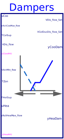
blockDampers
Information
This sequence sets the dampers for dual-duct terminal unit using mixing control with discharge flow sensor. The implementation is according to Section 5.13.5 of ASHRAE Guideline 36, May 2020. The calculation is done following the steps below.
-
When the zone state is cooling (
uCoo > 0), then the cooling loop outputuCooshall reset the supply airflow setpoint from the minimumVActMin_flowto cooling maximum setpointVActCooMax_flow. The cooling damper shall be modulated by a control loop to maintain the measured aiflowVDis_flowat setpoint. The heating damper shall be closedyHeaDam=0.-
If the cold-deck supply air temperature
TColSupfrom the cooling air handler is greater than room temperatureTZon, cooling supply airflow setpoint shall be no higher than the minimum.
-
If the cold-deck supply air temperature
-
When the zone state is deadband (
uCoo=0anduHea=0), the cooling airflow set pointVColDucDis_flow_Setshall be the minimum set pointVActMin_flow. The cooling damper shall be modulated by a control loop to maintain the measured cooling airflow at set point. The heating damper shall be closed. -
When the zone state is heating (
uHea > 0), then the heating loop outputuHeashall be mapped to the heating damper position. The cooling damper is modulated to maintain measured discharge airflow at the minimum airflow setpointVActMin_flow.-
If the hot-deck supply air temperature
THotSupfrom the heating air handler is less than room temperatureTZon, the heating damper shall be closed. -
Maximum heating airflow shall be limited by a reverse-acting P-only loop whose setpoint
is the heating maximum
VActHeaMax_flowand whose output is maximum heating damper position rangingfrom 0% to 100%.
-
If the hot-deck supply air temperature
-
Overriding above controls:
-
If heating air handler is not proven ON (
u1HeaAHU=false), the heating damper shall be closed (yHeaDam=0). -
If cooling air handler is not proven ON (
u1CooAHU=false), the cooling damper shall be closed (yCooDam=0).
-
If heating air handler is not proven ON (
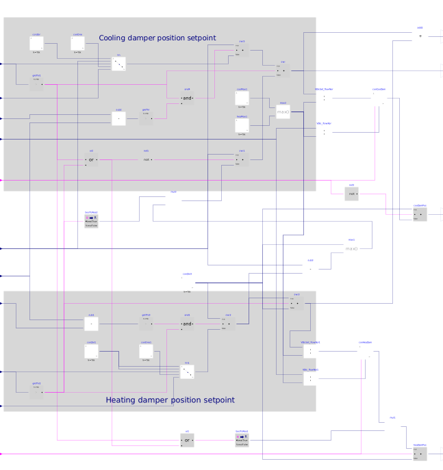
The sequences of controlling dampers position for dual-duct terminal unit using mixing control with inlet flow sensor are described in the following figure below.
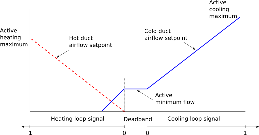
Note that when the zone is in heating state, the wordings in Section 5.13.5.1.c does not specify the flow setpoint. This causes confusion when implementing system request sequences that is specified in Section 5.13.8.4, which requires the flow setpoint. To avoid the confusion, the sequence was then implemented according to the plot above, which is Figure 5.13.5 in Guideline 36.
Parameters
| Type | Name | Default | Description |
|---|---|---|---|
| Real | VCooMax_flow | Design zone cooling maximum airflow rate | |
| Real | VHeaMax_flow | Design zone heating maximum airflow rate | |
| Buildings.Controls.OBC.CDL.Types.SimpleController | controllerTypeDam | Buildings.Controls.OBC.CDL.Types.SimpleController.PI | Type of controller |
| Real | kDam | 0.5 | Gain of controller for damper control |
| Real | TiDam | 300 | Time constant of integrator block for damper control |
| Real | TdDam | 0.1 | Time constant of derivative block for damper control |
| Real | kHeaMaxDam | 0.5 | Gain of controller for heating maximum damper control |
| Advanced | |||
| Real | dTHys | 0.25 | Temperature difference hysteresis below which the temperature difference will be seen as zero |
| Real | looHys | 0.05 | Loop output hysteresis below which the output will be seen as zero |
| Real | iniDam | 0.01 | Initial damper position when the damper control is enabled |
Connectors
Components
| Type | Name | Default | Description |
|---|---|---|---|
| Buildings.Controls.OBC.CDL.Logical.And | and4 | Logical and | |
| Buildings.Controls.OBC.CDL.Reals.Line | lin | Active airflow setpoint for cooling | |
| Buildings.Controls.OBC.CDL.Reals.Switch | swi | Output active cold duct airflow setpoint | |
| Buildings.Controls.OBC.CDL.Reals.Switch | swi5 | Airflow setpoint when it is in cooling state | |
| Buildings.Controls.OBC.CDL.Reals.Sources.Constant | conZer | Constant zero | |
| Buildings.Controls.OBC.CDL.Reals.Sources.Constant | conOne | Constant one | |
| Buildings.Controls.OBC.CDL.Reals.GreaterThreshold | greThr1 | Check if it is cooling state | |
| Buildings.Controls.OBC.CDL.Reals.GreaterThreshold | greThr | Check if supply air temperature is greater than room temperature | |
| Buildings.Controls.OBC.CDL.Reals.Subtract | sub2 | Calculate temperature difference between AHU supply air and room | |
| Buildings.Controls.OBC.CDL.Logical.Or | or2 | Cooing or heating state | |
| Buildings.Controls.OBC.CDL.Reals.GreaterThreshold | greThr2 | Check if it is heating state | |
| Buildings.Controls.OBC.CDL.Logical.Not | not1 | In deadband state | |
| Buildings.Controls.OBC.CDL.Reals.Switch | swi1 | Active cold duct airflow setpoint when it is in deadband state | |
| Buildings.Controls.OBC.CDL.Reals.Subtract | sub1 | Calculate temperature difference between AHU supply air and room | |
| Buildings.Controls.OBC.CDL.Reals.GreaterThreshold | greThr3 | Check if supply air temperature is less than room temperature | |
| Buildings.Controls.OBC.CDL.Logical.And | and1 | Logical and | |
| Buildings.Controls.OBC.CDL.Reals.Switch | swi2 | Airflow setpoint when it is in heating state | |
| Buildings.Controls.OBC.CDL.Reals.Switch | swi3 | Airflow setpoint when it is in heating state | |
| Buildings.Controls.OBC.CDL.Reals.Sources.Constant | conZer3 | Constant zero | |
| Buildings.Controls.OBC.CDL.Reals.Subtract | sub3 | Calculate flow rate difference between minimum flow setpoint and measured discharge flow | |
| Buildings.Controls.OBC.CDL.Reals.Max | max1 | Ensure positive flow | |
| Buildings.Controls.OBC.CDL.Conversions.BooleanToReal | booToRea2 | Convert boolean to real | |
| Buildings.Controls.OBC.CDL.Reals.Multiply | mul3 | Cold duct flow setpoint when in heating state | |
| Buildings.Controls.OBC.CDL.Reals.Divide | VDisSet_flowNor | Normalized setpoint for discharge volume flow rate | |
| Buildings.Controls.OBC.CDL.Reals.PIDWithReset | conCooDam | Cooling damper position controller | |
| Buildings.Controls.OBC.CDL.Reals.Divide | VDis_flowNor | Normalized discharge volume flow rate | |
| Buildings.Controls.OBC.CDL.Reals.Switch | cooDamPos | Output cooling damper position | |
| Buildings.Controls.OBC.CDL.Logical.Not | not3 | Not proven on | |
| Buildings.Controls.OBC.CDL.Reals.Divide | VDisSet_flowNor1 | Normalized setpoint for discharge volume flow rate | |
| Buildings.Controls.OBC.CDL.Reals.PIDWithReset | conHeaDam | Heating damper position controller | |
| Buildings.Controls.OBC.CDL.Reals.Divide | VDis_flowNor1 | Normalized discharge volume flow rate | |
| Buildings.Controls.OBC.CDL.Reals.Switch | heaDamPos | Output heating damper position | |
| Buildings.Controls.OBC.CDL.Logical.Or | or1 | Cooing or deadband state | |
| Buildings.Controls.OBC.CDL.Conversions.BooleanToReal | booToRea1 | Ensure heating damper is closed when it is in cooling or deadband state | |
| Buildings.Controls.OBC.CDL.Reals.Multiply | mul1 | Ensure heating damper is closed when it is in cooling or deadband state | |
| Buildings.Controls.OBC.CDL.Reals.Sources.Constant | conZer1 | Constant zero | |
| Buildings.Controls.OBC.CDL.Reals.Sources.Constant | conOne1 | Constant one | |
| Buildings.Controls.OBC.CDL.Reals.Line | lin1 | Active airflow setpoint for heating | |
| Buildings.Controls.OBC.CDL.Reals.Add | add2 | Total discharge airflow setpoint | |
| Buildings.Controls.OBC.CDL.Reals.Sources.Constant | cooMax1 | Cooling maximum flow | |
| Buildings.Controls.OBC.CDL.Reals.Sources.Constant | heaMax1 | Heating maximum flow | |
| Buildings.Controls.OBC.CDL.Reals.Max | max2 | Nominal flow |
Revisions
-
January 12, 2023, by Jianjun Hu:
Removed the parameterhave_preIndDamto exclude the option of using pressure independant damper.
This is for issue 3139. -
August 1, 2020, by Jianjun Hu:
First implementation.