This sequence sets the dampers for dual-duct terminal unit using mixing control with inlet flow sensor. The implementation is according to Section 5.12.5 of ASHRAE Guideline 36, May 2020. The calculation is done following the steps below.
uCoo > 0), then
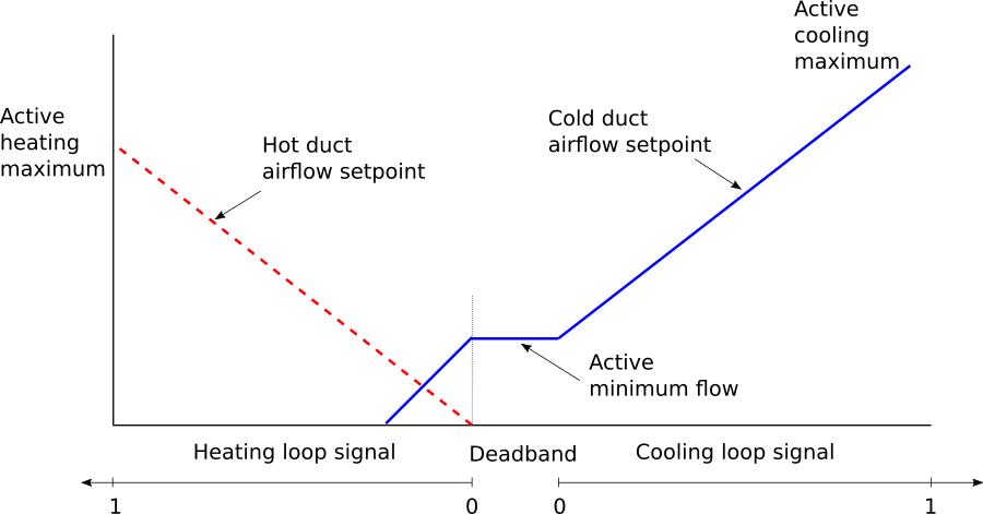
the cooling loop output uCoo shall reset the cooling
supply airflow setpoint VColDucDis_flow_Set from the
minimum VActMin_flow to cooling maximum setpoint
VActCooMax_flow. The cooling damper shall be modulated
by a control loop to maintain the measured cooling aiflow
VColDucDis_flow at setpoint. The heating damper shall
be closed yHeaDam=0.
TColSup
from the cooling air handler is greater than room temperature
TZon, cooling supply airflow setpoint shall be no
higher than the minimum.uCoo=0 and
uHea=0), the cooling airflow set point
VColDucDis_flow_Set shall be the minimum set point
VActMin_flow. The cooling damper shall be modulated by
a control loop to maintain the measured cooling airflow at set
point. The heating damper shall be closed.uHea > 0), then
the heating loop output uHea shall reset the heating
supply airflow setpoint VHotDucDis_flow_Set from zero
to heating maximum setpoint VActHeaMax_flow. The
heating damper shall be modulated by a control loop to maintain the
measured heating aiflow VHotDucDis_flow at setpoint.
The cooling damper shall be controlled to maintain the sum of the
measured inlet airflows at the minimum airflow set point
VActMin_flow.
THotSup
from the heating air handler is less than room temperature
TZon, heating supply airflow setpoint shall be no
higher than the minimum.u1HeaAHU=false), the heating damper shall be closed
(yHeaDam=0).u1CooAHU=false), the cooling damper shall be closed
(yCooDam=0).The sequences of controlling dampers position for dual-duct terminal unit using mixing control with inlet flow sensor are described in the following figure below.
have_preIndDam to exclude the
option of using pressure independant damper.