This sequence sets the fan status, damper and valve position for constant-volume series fan-powered terminal unit. The implementation is according to Section 5.9.5 of ASHRAE Guideline 36, May 2020. The calculation is done following the steps below.
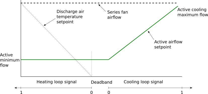
uCoo > 0), then
the cooling loop output uCoo shall be mapped to the
airflow setpoint from the minimum VActMin_flow to the
cooling maximum VActCooMax_flow airflow setpoints. The
heating coil is disabled (yVal=0).
TSup from the AHU is
greater than room temperature TZon, cooling supply
airflow setpoint shall be no higher than the minimum.uCoo=0 and
uHea=0), then the active airflow setpoint shall be the
minimum airflow setpoint VActMin_flow. The heating
coil is disabled (yVal=0).uHea > 0),
uHea increases from 0%
to 100%, it shall reset the discharge temperature
THeaDisSet from the current AHU setpoint temperature
TSupSet to a maximum of dTDisZonSetMax
above space temperature setpoint.VActMin_flow.u1Fan=true) for a fixed time delay (15 seconds), the
damper override is released.The sequences of controlling fan, damper position for constant-volume series fan-powered terminal unit are described in the following figure below.
As specified in Section 5.9.7 of ASHRAE Guideline 36, the airflow setpoint could be override by providing software switches that interlock to a system-level point to:
oveFloSet equals to 1, force the zone airflow
setpoint VPri_flow_Set to zero,oveFloSet equals to 2, force the zone airflow
setpoint VPri_flow_Set to zone cooling maximum airflow
rate VCooMax_flow,oveFloSet equals to 3, force the zone airflow
setpoint VPri_flow_Set to zone minimum airflow
setpoint VMin_flow.have_preIndDam to exclude the
option of using pressure independant damper.