blockSetpoints
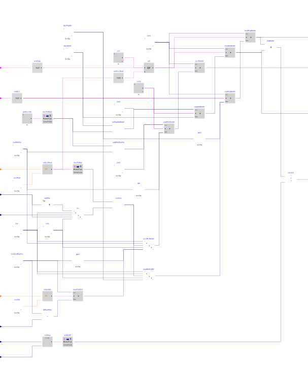
Information
This sequence sets the zone minimum outdoor air and minimum airflow setpoints, for compliance with the ventilation rate procedure of ASHRAE Standard 62.1. The implementation is according to ASHRAE Guideline36, Section 5.2.1.3. The calculation is done following the steps below.
1. For every zone that requires mechanical ventilation, the zone minimum outdoor airflows and set points shall be calculated depending on the governing standard or code for outdoor air requirements.
2. According to section 3.1.2 of Guideline 36, the zone minimum airflow setpoint
VMin_flow should be provided by designer.
Zone ventilation set points
According to Section 3.1.1.2 of Guideline 36,
-
The area component of the breathing zone outdoor airflow
VAreBreZon_flow.. -
The population component of the breathing zone outdoor airflow
VPopBreZon_flow.
Zone air distribution effectiveness
-
If the discharge air temperature
TDisat the terminal unit is less than or equal to zone space temperatureTZon, the effectiveness should be the zone cooling air distribution effectivenesszonDisEff_cooland defaults it to 1.0 if no value is scheduled. -
If the discharge air temperature
TDisat the terminal unit is greater than zone space temperatureTZon, the effectiveness should be the zone heating air distribution effectivenesszonDisEff_heatand defaults it to 0.8 if no value is scheduled.
Population component of the breathing zone outdoor airflow
The population component of the breathing zone outdoor airflow should normally equal to the value calculated above. However, it would be modified as noted in below.
Occupied minimum airflow
The occupied minimum airflow shall be equal to VMin_flow except as
noted in below.
Set points modification
The required zone outdoor airflow shall be calculated as the sum of area and population components of breathing zone outdoor airflow divided by air distribution effectiveness. The normal value of the area and population components are modified if any of the following conditions are met, in order from higher to lower priority:
- If the zone is any mode other than occupied mode, and for zones that have window switches and the window is open: the area and population components of breathing zone outdoor airflow, and the occupied minimum airflow rate should be zero.
- If the zone has an occupancy sensor, is unpopulated, and occupied-standby mode is permitted: the area and population components of breathing zone outdoor airflow, and the occupied minimum airflow rate should be zero.
-
Else, if the zone has an occupancy sensor, is unpopulated, but occupied-standby mode
is not permitted: the population components of breathing zone outdoor airflow
should be zero and the occupied minimum airflow rate should be
VMin_flow. -
If the zone has a CO2 sensor:
-
Specify CO2 setpoint
ppmCO2Setaccording to Section 3.1.1.3 of Guideline 36. - During occupied mode, a P-only loop shall maintain CO2 concentration at setpoint; reset from 0% at set point minus 200 PPM and to 100% at setpoint.
- Loop is disabled and output set to zero when the zone is not in occupied mode.
-
For cooling-only VAV terminal units, reheat VAV terminal units, constant-volume series
fan-powered terminal units, dual-duct VAV terminal units with mixing control and inlet
airflow sensors, dual-duct VAV terminal units with mixing control and a discharge
airflow sensor, or dual-duct VAV terminal units with cold-duct minimum control:
-
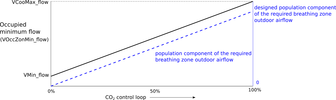
The CO2 control loop output shall reset both the occupied minimum airflow setpoint
and the population component of the required breathing zone outdoor airflow in parallel.
The occupied minimum airflow setpoint shall be reset from the zone minimum airflow
setpoint
VMin_flowat 0% loop output up to maximum cooling airflow setpointVCooMax_flowat 100% loop output. The population component of breathing zone outdoor airflow shall be reset from 0 L/s at 0% loop output up to the designed population component airflow setpoint at 100% loop output.
-
The CO2 control loop output shall reset both the occupied minimum airflow setpoint
and the population component of the required breathing zone outdoor airflow in parallel.
The occupied minimum airflow setpoint shall be reset from the zone minimum airflow
setpoint
-
For parallel fan-powered terminal units:
-
Determin the maximum flow rate for control CO2 level: when the zone state is cooling,
the maximum flow rate is equal to the maximum cooling airflow setpoint
VCooMax_flow; when the zone state is heating or deadband, the maximum flow rate is equal toVCooMax_flowminus the parallel fan airflowVParFan_flow. -
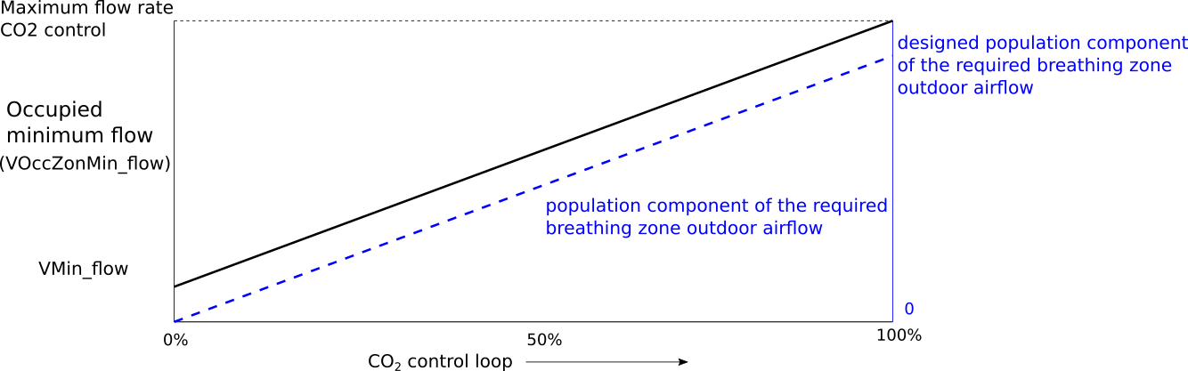
The occupied minimum airflow setpoint shall be reset from the zone minimum airflow
setpoint
VMin_flowat 0% loop output up to maximum cooling airflow setpoint determined by CO2 control level at 100% loop output. The population component of breathing zone outdoor airflow shall be reset from 0 L/s at 0% loop output up to the designed population component airflow setpoint at 100% loop output.
-
Determin the maximum flow rate for control CO2 level: when the zone state is cooling,
the maximum flow rate is equal to the maximum cooling airflow setpoint
-
Specify CO2 setpoint
-
For single zoneVAV air handler unit: the minimum outdoor air setpoint is equal to
the breathing zone outdoor airflow setpoint.
-
If the zone has CO2 sensor, the CO2 control loop output shall reset
the population component of the required breathing zone outdoor airflow from 0 L/s
at 0% loop output up to the designed population component airflow setpoint at
100% loop output.

- If the zone dose not have CO2 sensor, the minimum outdoor air setpoint is equal to the design breathing zone outdoor airflow setpoint.
-
If the zone has CO2 sensor, the CO2 control loop output shall reset
the population component of the required breathing zone outdoor airflow from 0 L/s
at 0% loop output up to the designed population component airflow setpoint at
100% loop output.
Parameters
| Type | Name | Default | Description |
|---|---|---|---|
| Boolean | have_winSen | false | True: the zone has window sensor |
| Boolean | have_occSen | false | True: the zone has occupancy sensor |
| Boolean | have_CO2Sen | false | True: the zone has CO2 sensor |
| Boolean | have_typTerUni | false | True: the zone has typical terminal units and CO2 sensor |
| Boolean | have_parFanPowUni | false | True: the zone has parallel fan-powered terminal unit and CO2 sensor |
| Boolean | have_SZVAV | false | True: it is single zone VAV AHU system with CO2 sensor |
| Boolean | permit_occStandby | true | True: occupied-standby mode is permitted |
| Design conditions | |||
| Real | VAreBreZon_flow | Design area component of the breathing zone outdoor airflow | |
| Real | VPopBreZon_flow | Design population component of the breathing zone outdoor airflow | |
| Real | VMin_flow | Design zone minimum airflow setpoint | |
| Real | VCooMax_flow | 0.025 | Design zone cooling maximum airflow rate |
| Advanced › Distribution effectiveness | |||
| Real | zonDisEff_cool | 1.0 | Zone cooling air distribution effectiveness |
| Real | zonDisEff_heat | 0.8 | Zone heating air distribution effectiveness |
| Advanced | |||
| Real | dTHys | 0.25 | Temperature difference hysteresis below which the temperature difference will be seen as zero |
Connectors
Revisions
-
August 12, 2020, by Jianjun Hu:
First implementation.