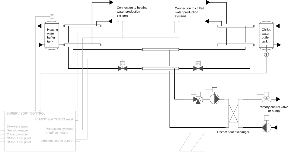
This is a base model providing the hydronic configuration for an
energy transfer station as described in the schematics below. It is
typically used to integrate systems providing both heating water
and chilled water, such as heat recovery chillers. Furthermore, it
can be connected to an adjustable number (nSouAmb) of
systems serving as ambient sources (including the district heat
exchanger).
Models that extend this base class must
nSouAmb, the number of heating water production
systems nSysHea, and the number of chilled water
production systems nSysCoo (by default
nSysCoo=nSysHea which corresponds to a configuration
where both productions are ensured by the same system, such as a
heat recovery chiller),mCon_flow_nominal (array) of the components
colChiWat, colHeaWat and
colAmbWat. The connection index 1 for the
components colChiWat and colHeaWat is
reserved for the connection with the ambient source circuit. It
increases with the distance from the buffer tank. The connection
index 1 for the component colAmbWat is
reserved for the connection with the district heat exchanger. Note
that the order of the connections has no impact on the flow
distribution as the connections are in parallel.Note that the model includes a pressure boundary condition which
is shared between the hot water and chilled water circuits, the two
circuits being hydronically connected.