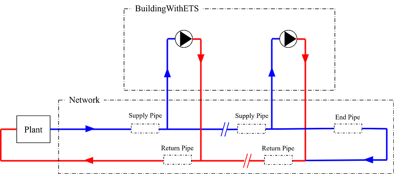
Example model for district cooling system with an electric chiller
plant and a direct controlled ETS at each building
This model illustrates an example of district cooling system,
consisting of a cooling plant with parallel electric chillers (
Buildings.DHC.Plants.Cooling.ElectricChillerParallel),
a two-pipe distribution network with plug flow pipes ( Buildings.DHC.Networks.Distribution2PipePlugFlow_v),
and time series building load that have directly connected ETS with
the chilled water return temperatures controlled above a minimum
threshold ( Buildings.DHC.Loads.Cooling.BuildingTimeSeriesWithETS).
This configuration is illustrated in the schematic below.
Contents
| Name |
Description |
 Medium Medium |
Medium model for water |
- August 22, 2023, by Michael Wetter:
Changed call to loadResources. This is needed for
Dymola 2024x beta1 on Linux.
- January 2, 2023, by Kathryn Hinkelman:
Revised chilled water pump controls to be constant speed and
running 1-and-1 with the chillers.
Changed building-side ets from direct uncontrolled to
controlled.
Revised distribution network from fixed resistance pipes to plug
flow pipes.
- December 21, 2022, by Kathryn Hinkelman:
Corrected dpMea location to be at the terminal
building. Removed in-building pumping for direct uncontrolled ETS
example.
This is for
#2912.
- December 18, 2022, by Kathryn Hinkelman:
Relocated dp sensor for CHW pump control to most distal building.
This is for
#2912.
- March 20, 2022, by Chengnan Shi:
First implementation.
Generated at 2026-07-21T20:30:55Z by OpenModelicaOpenModelica 1.27.0 using
GenerateDoc.mos