modelAllElectricCWStorage
Extends from BaseClasses.PartialPlant (Partial class for modeling a plant).
Information
This model represents a combined heating and cooling plant where chilled water is produced by cooling-only chillers and heat recovery chillers, hot water is produced by heat recovery chillers, and a thermal energy storage tank is integrated in the condenser water circuit to maximize heat recovery ("Tank Charge/Discharge" operating mode). Cooling towers allow rejecting excess heat from the condenser loop ("Heat Rejection" operating mode). Air-source heat pumps allow injecting heat into the condenser loop ("Charge Assist" operating mode).
This model has been developed based on the publication by B. Gill (2021) and further discussions with Taylor Engineers.
Abbreviations and naming conventions
The following abbreviations are used in the documentation of this
model and of its components.
| Abbreviation | Description |
|---|---|
| AI | Analog input (integer or real) |
| AO | Analog output (integer or real) |
| CHW | Chilled water |
| CT | Cooling tower |
| CW | Condenser water |
| CWC | Condenser water circuit serving chiller and HRC condenser barrel |
| CWE | Condenser water circuit serving HRC evaporator barrel |
| DI | Digital input (Boolean) |
| DO | Digital output (Boolean) |
| HP | Heat pump |
| HR | Heat recovery |
| HRC | Heat recovery chiller |
| HW | Hot water |
| VFD | Variable frequency drive |
To clearly distinguish cooling-only chillers from heat recovery chillers, the term "chiller" is used systematically to refer to cooling-only chillers whereas the abbreviation "HRC" is used systematically to refer to heat recovery chillers.
Each HRC can operate under the following modes. In cascading heating mode, the condenser barrel is connected to the HW loop and the evaporator barrel is connected to the CW loop (CWE circuit). The onboard controller controls the HRC to track a HW supply temperature setpoint at condenser outlet. In cascading cooling mode, the condenser barrel is connected to the CW loop (CWC circuit) and the evaporator barrel is connected to the CHW loop. The onboard controller controls the HRC to track a CHW supply temperature setpoint at evaporator outlet. In direct heat recovery mode, the condenser barrel is connected to the HW loop and the evaporator barrel is connected to the CHW loop. The onboard controller controls the HRC to track a HW supply temperature setpoint at condenser outlet while the plant supervisory controller maintains the CHW supply temperature at setpoint by modulating the evaporator flow rate or the condenser entering temperature.
System schematic
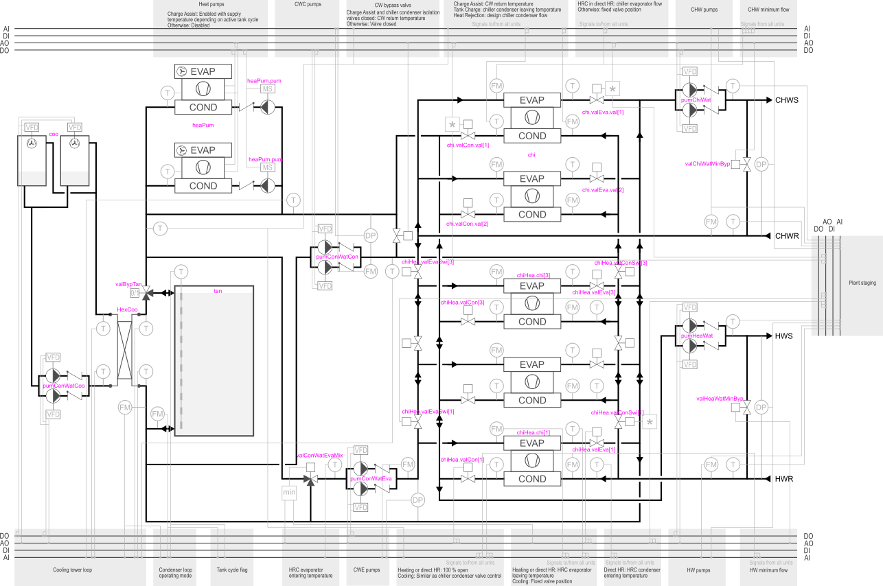
The schematic below represents a configuration of the system with two chillers and three HRCs. The equipment tags correspond to the component names in the plant model. The control points used by each control function are represented at the intersection of the gray area that describes the function and the four bus lines corresponding to the different control point categories (AI, DI, AO, DO). For the sake of clarity, control logic that is duplicated between multiple units (for instance the chiller isolation valve control) is only illustrated for one unit. The detailed description of each control function is available in the documentation of Buildings.DHC.Plants.Combined.Controls.Controller. For an overview of the different operating modes and the design principles of such a system, the user may refer to the article by B. Gill (2021).
Control points
Cooling and heating Enable signals
The cooling and heating Enable signals u1Coo and u1Hea
shall be computed outside of the plant model, for instance based on a time schedule.
CHW and HW supply temperature and differential pressure setpoint
Those setpoints are provided as control inputs. Ideally, a reset logic based on consumer valve requests should be implemented to adapt those setpoints to the demand.
Details
Sizing considerations
Sizing the TES tank and the heat pumps is a joint optimization problem under the constraint that on a design heating day, heating loads can be met using both the recovered heat and the heat added to the tank by the heat pumps. As stated by B. Gill (2021), increasing the tank capacity generally improves plant efficiency by providing more opportunity for heat recovery. Tank capacity should therefore be maximized under the limit corresponding to the amount of heat that can be recovered over the day.
The model is configured by default with a tank that is sized to store
the heat needed to operate the HRCs during 3 h at peak heating
load with a ΔT covering the two temperature cycles specified
with the parameter TTanSet (heels and thermocline neglected).
This default can be overwritten.
TES tank
The tank is assumed to be integrated without pressure separation, i.e., the operating level of the tank sets the system pressure and no pressure sustaining valve or discharge pump is included. The operating level is approximated as equal to the tank height. A default height to diameter ratio of 2 is also taken into account (designers tend to favor a height to diameter ratio above 1.5 in order to minimize the volume of the thermocline which is considered useless). No high limit is considered for the tank mass flow rate.
CHW and HW minimum flow bypass valve
As per standard practice, the bypass valve is sized for the highest chiller minimum flow. The bypass valve model is configured with a pressure drop varying linearly with the flow rate, as opposed to a quadratic dependency usually considered for a turbulent flow regime. This is because the whole plant model contains large nonlinear systems of equations, and this configuration limits the risk of solver failure while reducing the time to solution. This has no significant impact on the operating point of the circulation pumps due to the control loop that modulates the valve opening to generate enough pressure differential at the chiller boundaries to allow for minimum flow circulation. So whatever the modeling assumptions for the bypass valve, the control loop ensures that the valve creates the adequate pressure drop and bypass flow, which will simply be reached at a different valve opening with the above simplification.
Cooling tower circuit
The design heat flow rate used to size the cooling towers and the intermediary heat exchanger corresponds to the heat flow rate rejected by all HRCs operating in cascading cooling mode and all chillers operating at design conditions. The cooling towers are sized with a default approach of 3 K to the design wetbulb temperature. The intermediary heat exchanger is sized with a default approach of 2 K.
Chiller and HRC performance data
The chiller performance data should cover the CW temperature levels
reached when the plant is operating in Heat Rejection mode.
The parameter TCasConEnt_nominal (set with a final assignment)
provides the maximum CW supply (condenser entering) temperature in this
operating mode.
The HRC performance data should cover the HRC lift envelope,
that is when the HRC is operating in direct heat recovery mode,
producing CHW and HW at their setpoint value at full load.
References
Brandon Gill, P.E., Taylor Engineers, Alameda, CA, USA.
Solving the large building all-electric heating problem.
ASHRAE Journal, October 2021.
Parameters
| Type | Name | Default | Description |
|---|---|---|---|
| Boolean | have_fue (from PartialPlant) | nFue > 0 | Set to true if the plant has fuel use |
| Buildings.Fluid.Data.Fuels.Generic[nFue] | fue (from PartialPlant) | Fuel type | |
| Fluid.Chillers.Data.ElectricReformulatedEIR.Generic | datChi | ||
| Modelica.Units.SI.HeatFlowRate | QChiWat_flow_nominal | chi.QChiWat_flow_nominal + chiHea.QChiWat_flow_nominal | Design plant cooling heat flow rate (all units) |
| Fluid.Chillers.Data.ElectricReformulatedEIR.Generic | datChiHea | ||
| Modelica.Units.SI.Temperature | TCasHeaEnt_nominal | TTanSet[2, 2] | Design evaporator entering temperature in cascading heating mode |
| Modelica.Units.SI.Temperature | TCasCooEnt_nominal | TConWatCooSup_nominal + dTHexCoo_nominal | Design condenser entering temperature in cascading cooling mode |
| Modelica.Units.SI.MassFlowRate | mConWatCon_flow_nominal | chi.mConWat_flow_nominal + chiHea.mConWat_flow_nominal | Design total CW mass flow rate through condenser barrels (all units) |
| Configuration | |||
| Buildings.DHC.Types.DistrictSystemType | typ (from PartialPlant) | Buildings.DHC.Types.DistrictSystemType.CombinedGeneration2to4 | Type of district system |
| Boolean | have_fan (from PartialPlant) | false | Set to true if fan power is computed |
| Boolean | have_pum (from PartialPlant) | false | Set to true if pump power is computed |
| Boolean | have_eleHea (from PartialPlant) | false | Set to true if the plant has electric heating system |
| Integer | nFue (from PartialPlant) | 0 | Number of fuel types (0 means no combustion system) |
| Boolean | have_eleCoo (from PartialPlant) | false | Set to true if the plant has electric cooling system |
| Boolean | have_weaBus (from PartialPlant) | false | Set to true to use a weather bus |
| Assumptions | |||
| Boolean | allowFlowReversal (from PartialPlant) | false | Set to true to allow flow reversal in service lines |
| CHW loop and cooling-only chillers | |||
| Integer | nChi | Number of units operating at design conditions | |
| Integer | nPumChiWat | max(nChi, nChiHea) | Number of CHW pumps operating at design conditions |
| Modelica.Units.SI.MassFlowRate | mChiWatChi_flow_nominal | datChi.mEva_flow_nominal | Design chiller CHW mass flow rate (each unit) |
| Modelica.Units.SI.MassFlowRate | mChiWatChi_flow_min | 0.6*mChiWatChi_flow_nominal | Chiller CHW minimum mass flow rate (each unit) |
| Modelica.Units.SI.MassFlowRate | mConWatChi_flow_nominal | datChi.mCon_flow_nominal | Design chiller CW mass flow rate (each unit) |
| Modelica.Units.SI.PressureDifference | dpChiWatSet_max | Design (maximum) CHW differential pressure setpoint | |
| Modelica.Units.SI.PressureDifference | dpEvaChi_nominal | 5E4 | Design evaporator pressure drop (each unit) |
| Modelica.Units.SI.PressureDifference | dpConChi_nominal | 5E4 | Design condenser pressure drop (each unit) |
| Modelica.Units.SI.PressureDifference | dpPumChiWat_nominal | 1.1*(dpChiWatSet_max + max(dpEvaChi_nominal + chi.valEva.dpValve_nominal, dpEvaChiHea_nominal + max(chiHea.valEva.dpValve_nominal) + sum(chiHea.valEvaSwi.dpValve_nominal))) | Design head of CHW pump(each unit) |
| Modelica.Units.SI.Temperature | TChiWatSup_nominal | max(chi.TChiWatSup_nominal, chiHea.TChiWatSup_nominal) | Design (minimum) CHW supply temperature |
| Modelica.Units.SI.Temperature | TChiWatRet_nominal | TChiWatSup_nominal - QChiWat_flow_nominal/mChiWat_flow_nominal/cp_default | Design (maximum) CHW return temperature |
| Modelica.Units.SI.MassFlowRate | mChiWat_flow_nominal | nChi*mChiWatChi_flow_nominal + nChiHea*mChiWatChiHea_flow_nominal | Design CHW mass flow rate (all units) |
| Modelica.Units.SI.TemperatureDifference | dTLifChi_min | 10 | Minimum chiller lift at minimum load |
| Modelica.Units.SI.TemperatureDifference | dTLifChi_nominal | TTanSet[1, 2] + 5 - TChiWatSup_nominal | Design chiller lift |
| HW loop and heat recovery chillers | |||
| Integer | nChiHea | Number of units operating at design conditions | |
| Integer | nPumHeaWat | nChiHea | Number of HW pumps operating at design conditions |
| Modelica.Units.SI.MassFlowRate | mChiWatChiHea_flow_nominal | datChiHea.mEva_flow_nominal | Design HRC CHW mass flow rate (each unit) |
| Modelica.Units.SI.MassFlowRate | mChiWatChiHea_flow_min | 0.6*mChiWatChiHea_flow_nominal | HRC CHW minimum mass flow rate (each unit) |
| Modelica.Units.SI.MassFlowRate | mHeaWatChiHea_flow_min | 0.6*mConWatChiHea_flow_nominal | HRC HW minimum mass flow rate (each unit) |
| Modelica.Units.SI.MassFlowRate | mConWatChiHea_flow_nominal | datChiHea.mCon_flow_nominal | Design HRC CW mass flow rate (each unit) |
| Modelica.Units.SI.PressureDifference | dpHeaWatSet_max | Design (maximum) HW differential pressure setpoint | |
| Modelica.Units.SI.PressureDifference | dpEvaChiHea_nominal | 5E4 | Design evaporator pressure drop (each unit) |
| Modelica.Units.SI.PressureDifference | dpConChiHea_nominal | 5E4 | Design condenser pressure drop (each unit) |
| Modelica.Units.SI.PressureDifference | dpPumHeaWat_nominal | 1.1*(dpHeaWatSet_max + dpConChiHea_nominal + max(chiHea.valCon.dpValve_nominal) + sum(chiHea.valConSwi.dpValve_nominal)) | Design head of HW pump(each unit) |
| Modelica.Units.SI.Temperature | THeaWatSup_nominal | chiHea.THeaWatSup_nominal | Design (maximum) HW supply temperature |
| Modelica.Units.SI.Temperature | THeaWatRet_nominal | THeaWatSup_nominal - QHeaWat_flow_nominal/mHeaWat_flow_nominal/cp_default | Design (minimum) HW return temperature |
| Modelica.Units.SI.HeatFlowRate | QHeaWat_flow_nominal | chiHea.QHeaWat_flow_nominal | Design heating heat flow rate (all units) |
| Modelica.Units.SI.MassFlowRate | mHeaWat_flow_nominal | chiHea.mConWat_flow_nominal | Design HW mass flow rate (all units) |
| CW loop, TES tank and heat pumps | |||
| Integer | nHeaPum | Number of heat pumps operating at design conditions | |
| Integer | nPumConWatCon | max(nChi, nChiHea) | Number of CW pumps serving condenser barrels at design conditions |
| Integer | nPumConWatEva | nChiHea | Number of CW pumps serving evaporator barrels at design conditions |
| Modelica.Units.SI.PressureDifference | dpConWatConSet_max | max(dpConChi_nominal + chi.valCon.dpValve_nominal, dpConChiHea_nominal + max(chiHea.valCon.dpValve_nominal) + sum(chiHea.valConSwi.dpValve_nominal)) | Design (maximum) CW condenser loop differential pressure setpoint |
| Modelica.Units.SI.PressureDifference | dpConWatEvaSet_max | dpEvaChiHea_nominal + max(chiHea.valEva.dpValve_nominal) + sum(chiHea.valEvaSwi.dpValve_nominal) | Design (maximum) CW evaporator loop differential pressure setpoint |
| Modelica.Units.SI.PressureDifference | dpPumConWatCon_nominal | 1.1*(dpConWatConSet_max + max(dpHexCoo_nominal, dpTan_nominal)) | Design head of CW pump serving condenser barrels (each unit) |
| Modelica.Units.SI.PressureDifference | dpPumConWatEva_nominal | 1.1*(dpConWatEvaSet_max + dpTan_nominal) | Design head of CW pump serving evaporator barrels (each unit) |
| Modelica.Units.SI.MassFlowRate | mConWatEva_flow_nominal | chiHea.mChiWat_flow_nominal | Design total CW mass flow rate through evaporator barrels (all units) |
| Modelica.Units.SI.Volume | VTan | -chiHea.QEvaCasHea_flow_nominal*3*3600/(max(TTanSet) - min(TTanSet))/cp_default/rho_default | Tank volume |
| Modelica.Units.SI.Length | hTan | (16*VTan/Modelica.Constants.pi)^(1/3) | Height of tank (without insulation) |
| Real | fraUslTan | ((max(TTanSet[2]) - min(TTanSet))/(max(TTanSet) - min(TTanSet))*1 + 1)/hTan | Useless fraction of TES |
| Modelica.Units.SI.Length | dInsTan | Thickness of insulation | |
| Modelica.Units.SI.ThermalConductivity | kInsTan | 0.04 | Specific heat conductivity of insulation |
| Modelica.Units.SI.Temperature[2,2] | TTanSet | {{15 + 273.15, 25 + 273.15}, {TChiWatSup_nominal, 15 + 273.15}} | Tank temperature setpoints: 2 cycles with 2 setpoints |
| Modelica.Units.SI.PressureDifference | dpTan_nominal | 1E3 | Design pressure drop through TES tank |
| Fluid.HeatPumps.Data.EquationFitReversible.Generic | datHeaPum | Heat pump parameters (each unit) | |
| Advanced › CW loop, TES tank and heat pumps | |||
| Integer | nSegTan | 10 | Number of volume segments |
| Cooling tower loop | |||
| Integer | nCoo | Number of cooling tower cells operating at design conditions | |
| Modelica.Units.SI.MassFlowRate | mConWatCoo_flow_nominal | mConWatCon_flow_nominal | Design CT CW mass flow rate (all units) |
| Modelica.Units.SI.PressureDifference | dpConWatCooFri_nominal | Design CW flow-friction losses through tower and piping only (without elevation head or valve) | |
| Modelica.Units.SI.MassFlowRate | mAirCooUni_flow_nominal | Design CT air mass flow rate (each unit) | |
| Modelica.Units.SI.Temperature | TWetBulCooEnt_nominal | Design CT entering air wetbulb temperature | |
| Modelica.Units.SI.Temperature | TConWatCooRet_nominal | TConWatCooSup_nominal + abs(QHexCoo_flow_nominal)/mConWatCoo_flow_nominal/cpConWatCoo_default | Design CT CW return temperature (tower entering) |
| Modelica.Units.SI.Temperature | TConWatCooSup_nominal | TWetBulCooEnt_nominal + 3 | Design CT CW supply temperature (tower leaving) |
| Modelica.Units.SI.Power | PFanCoo_nominal | CT fan power (each unit) | |
| Integer | nPumConWatCoo | nCoo | Number of CW pumps serving cooling towers at design conditions |
| Modelica.Units.SI.PressureDifference | dpPumConWatCoo_nominal | 1.1*(dpHexCoo_nominal + dpConWatCooFri_nominal) | Design head of CW pump serving cooling towers (each unit) |
| Modelica.Units.SI.TemperatureDifference | dTHexCoo_nominal | 2 | Design heat exchanger approach |
| Modelica.Units.SI.PressureDifference | dpHexCoo_nominal | 3E4 | Design pressure drop through heat exchanger (same on both sides) |
| Modelica.Units.SI.HeatFlowRate | QHexCoo_flow_nominal | -(chi.QConWat_flow_nominal + chiHea.QConCasCoo_flow_nominal) | Design cooling heat flow rate of heat exchanger (<0) |
| Dynamics › Conservation equations | |||
| Modelica.Fluid.Types.Dynamics | energyDynamics | Modelica.Fluid.Types.Dynamics.DynamicFreeInitial | Type of energy balance: dynamic (3 initialization options) or steady state |
| Dynamics › Dynamics of actuators and pump motors | |||
| Boolean | use_strokeTime | energyDynamics <> Modelica.Fluid.Types.Dynamics.SteadyState | Time needed to open or close valve |
| Dynamics › Filtered signal for actuators | |||
| Boolean | use_riseTime | energyDynamics <> Modelica.Fluid.Types.Dynamics.SteadyState | Time needed to change motor speed |
Connectors
Components
| Type | Name | Default | Description |
|---|---|---|---|
| Subsystems.ChillerGroup | chi | Cooling-only chillers | |
| Subsystems.MultiplePumpsSpeed | pumChiWat | Primary CHW pumps | |
| Fluid.FixedResistances.Junction | junChiWatSup | Fluid junction | |
| Fluid.FixedResistances.Junction | junChiWatRet | Fluid junction | |
| Fluid.FixedResistances.Junction | junChiWatChiHeaRet | Fluid junction | |
| Fluid.FixedResistances.Junction | junChiWatChiHeaSup | Fluid junction | |
| Fluid.Actuators.Valves.TwoWayLinear | valChiWatMinByp | CHW minimum flow bypass valve | |
| Fluid.Sensors.RelativePressure | dpChiWat | CHW differential pressure (local sensor hardwired to plant controller) | |
| Fluid.Sensors.TemperatureTwoPort | TChiWatPriRet | Primary CHW return temperature | |
| Fluid.Sensors.MassFlowRate | mChiWatPri_flow | Primary CHW mass flow rate | |
| Fluid.Sensors.TemperatureTwoPort | TChiWatSup | CHW supply temperature | |
| Subsystems.ChillerHeatRecoveryGroup | chiHea | Heat recovery chillers | |
| Subsystems.MultiplePumpsSpeed | pumHeaWat | Primary HW pumps | |
| Fluid.FixedResistances.Junction | junHeaWatSup | Fluid junction | |
| Fluid.FixedResistances.Junction | junHeaWatRet | Fluid junction | |
| Fluid.Actuators.Valves.TwoWayLinear | valHeaWatMinByp | HW minimum flow bypass valve | |
| Fluid.Sensors.RelativePressure | dpHeaWat | HW differential pressure (local sensor hardwired to plant controller) | |
| Fluid.Sensors.TemperatureTwoPort | THeaWatPriRet | Primary HW return temperature | |
| Fluid.Sensors.TemperatureTwoPort | THeaWatSup | HW supply temperature | |
| Fluid.Sensors.MassFlowRate | mHeaWatPri_flow | Primary HW mass flow rate | |
| Subsystems.MultiplePumpsSpeed | pumConWatCon | CW pumps serving condenser barrels | |
| Subsystems.MultiplePumpsSpeed | pumConWatEva | CW pumps serving evaporator barrels | |
| Fluid.FixedResistances.Junction | junConWatEnt | Fluid junction | |
| Fluid.Storage.Stratified | tan | TES tank | |
| Fluid.Sources.Boundary_pT | bouConWat | CW pressure boundary condition prescribed by tank operating level | |
| Fluid.FixedResistances.Junction | junConWatTanEnt | Fluid junction | |
| Fluid.FixedResistances.Junction | junConWatLvg | Fluid junction | |
| Modelica.Thermal.HeatTransfer.Sensors.TemperatureSensor[nSegTan] | TTan | TES tank temperature sensor gateway | |
| HeatTransfer.Sources.PrescribedTemperature | out | Outdoor temperature | |
| Fluid.FixedResistances.Junction | junConWatHeaPumEnt | Fluid junction | |
| Fluid.FixedResistances.Junction | junConWatHeaPumLvg | Fluid junction | |
| Subsystems.HeatPumpGroup | heaPum | Heat pumps | |
| Fluid.FixedResistances.Junction | junConWatTanLvg | Fluid junction | |
| Fluid.HeatExchangers.PlateHeatExchangerEffectivenessNTU | hexCoo | Heat exchanger with cooling tower circuit | |
| Subsystems.CoolingTowerGroup | coo | Cooling towers | |
| Fluid.Actuators.Valves.ThreeWayLinear | valBypTan | TES tank bypass valve | |
| Fluid.Sources.Boundary_pT | bouConWatCoo | CW pressure boundary condition prescribed by CT elevation head | |
| Subsystems.MultiplePumpsSpeed | pumConWatCoo | Cooling tower pumps | |
| Fluid.Sensors.TemperatureTwoPort | TConWatEvaEnt | HRC evaporator entering CW temperature | |
| Buildings.DHC.Plants.Combined.Controls.Controller | ctl | Controller | |
| Modelica.Blocks.Sources.RealExpression | sumPHea | Sum up power drawn from all subsystems | |
| Modelica.Blocks.Sources.RealExpression | sumPCoo | Sum up power drawn from all subsystems | |
| Modelica.Blocks.Sources.RealExpression | sumPFan | Sum up power drawn from all subsystems | |
| Modelica.Blocks.Sources.RealExpression | sumPPum | Sum up power drawn from all subsystems | |
| Fluid.Sensors.RelativePressure | dpConWatEva | CW evaporator loop differential pressure | |
| Fluid.Sensors.RelativePressure | dpConWatCon | CW condenser loop differential pressure | |
| Fluid.Sensors.MassFlowRate | mConWatEva_flow | CW evaporator loop mass flow rate | |
| Fluid.Sensors.MassFlowRate | mConWatCon_flow | CW condenser loop mass flow rate | |
| Fluid.Sensors.MassFlowRate | mConWatOutTan_flow | Mass flow rate out of lower port of TES tank (>0 when charging) | |
| Fluid.Sensors.TemperatureTwoPort | TConWatConChiLvg | Chiller and HRC leaving CW temperature | |
| Fluid.Sensors.TemperatureTwoPort | TConWatConChiEnt | Chiller and HRC entering CW temperature | |
| Fluid.Sensors.TemperatureTwoPort | TConWatCooSup | Cooling tower loop CW supply temperature | |
| Fluid.Sensors.TemperatureTwoPort | TConWatCooRet | Cooling tower loop CW return temperature | |
| Fluid.Sensors.TemperatureTwoPort | TConWatHexCooEnt | HX entering CW temperature | |
| Fluid.Sensors.TemperatureTwoPort | TConWatHexCooLvg | HX leaving CW temperature | |
| Fluid.Actuators.Valves.ThreeWayLinear | valConWatEvaMix | HRC evaporator CW mixing valve | |
| Fluid.FixedResistances.Junction | junConWatEvaLvg | Fluid junction | |
| Fluid.Sensors.TemperatureTwoPort | TConWatConRet | Condenser loop CW return temperature | |
| Fluid.Sensors.TemperatureTwoPort | TConWatHeaPumEnt | HP entering CW temperature | |
| Fluid.Sensors.TemperatureTwoPort | TConWatHeaPumLvg | HP leaving CW temperature | |
| Fluid.Sensors.MassFlowRate | mConWatHexCoo_flow | CW mass flow rate through secondary (plant) side of HX | |
| Fluid.Actuators.Valves.TwoWayLinear | valConWatByp | CW chiller bypass valve |
Contents
| Name | Description |
|---|---|
 MediumAir MediumAir | Air medium |
 MediumConWatCoo MediumConWatCoo |
Revisions
-
February 24, 2023, by Antoine Gautier:
First implementation.