modelTwoPortRLC_N
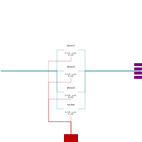
Extends from Modelica.Electrical.Analog.Interfaces.ConditionalHeatPort (Partial model to include a conditional HeatPort in order to describe the power loss via a thermal network), Buildings.Electrical.AC.ThreePhasesUnbalanced.Interfaces.TwoPort_N (Partial model interface for a two port component with neutral cable).
Information
RLC line model (T-model) that connects two AC three-phase unbalanced interfaces with neutral line. This model can be used to represent a cable in a three-phase unbalanced AC system.
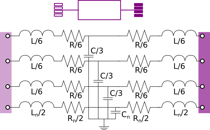
The model represents the lumped impedances as shown in the figure above. Assuming that the overall cable has a resistance R, an inductance L, and a capacitance C, each line has an inductance equal to L/3, a resistance equal to R/3 and a capacity equal to C/3.
The resistance, capacitance and inductance of the neutral cable are defined separately using the parameters
Rn Cn, and Ln.
Parameters
| Type | Name | Default | Description |
|---|---|---|---|
| Boolean | useHeatPort (from ConditionalHeatPort) | false | = true, if heatPort is enabled |
| SI.Temperature | T (from ConditionalHeatPort) | 293.15 | Fixed device temperature if useHeatPort = false |
| Modelica.Units.SI.Resistance | R | Resistance at temperature T_ref | |
| Modelica.Units.SI.Resistance | Rn | Resistance of neutral cable at temperature T_ref | |
| Modelica.Units.SI.Capacitance | C | Capacity | |
| Modelica.Units.SI.Capacitance | Cn | Capacityof neutral cable | |
| Modelica.Units.SI.Inductance | L | Inductance | |
| Modelica.Units.SI.Inductance | Ln | Inductance of neutral cable | |
| Modelica.Units.SI.Temperature | T_ref | 298.15 | Reference temperature |
| Modelica.Units.SI.Temperature | M | 507.65 | Temperature constant (R_actual = R*(M + T_heatPort)/(M + T_ref)) |
| Modelica.Units.SI.Voltage[2] | Vc1_start | V_nominal/sqrt(3)*{1, 0} | Initial voltage phasor of the capacitance located in the middle of phase 1 |
| Modelica.Units.SI.Voltage[2] | Vc2_start | V_nominal/sqrt(3)*{-1/2, -sqrt(3)/2} | Initial voltage phasor of the capacitance located in the middle of phase 1 |
| Modelica.Units.SI.Voltage[2] | Vc3_start | V_nominal/sqrt(3)*{-1/2, +sqrt(3)/2} | Initial voltage phasor of the capacitance located in the middle of phase 1 |
| Modeling assumption | |||
| Buildings.Electrical.Types.Load | mode | Buildings.Electrical.Types.Load.FixedZ_steady_state | Type of model (e.g., steady state, dynamic, prescribed power consumption, etc.) |
| Nominal conditions | |||
| Modelica.Units.SI.Voltage | V_nominal | Nominal voltage (V_nominal >= 0) | |
Connectors
| Type | Name | Default | Description |
|---|---|---|---|
| Modelica.Thermal.HeatTransfer.Interfaces.HeatPort_a | heatPort (from ConditionalHeatPort) | Conditional heat port | |
| Terminal4_p | terminal_p (from TwoPort_N) | Electric terminal side p | |
| Terminal4_n | terminal_n (from TwoPort_N) | Electric terminal side n |
Components
| Type | Name | Default | Description |
|---|---|---|---|
| SI.Power | LossPower (from ConditionalHeatPort) | Loss power leaving component via heatPort | |
| SI.Temperature | T_heatPort (from ConditionalHeatPort) | Temperature of heatPort | |
| OnePhase.Lines.TwoPortRLC | phase1 | Impedance line 1 | |
| OnePhase.Lines.TwoPortRLC | phase2 | Impedance line 2 | |
| OnePhase.Lines.TwoPortRLC | phase3 | Impedance line 3 | |
| OnePhase.Lines.TwoPortRLC | neutral | Neutral line RLC model |
Revisions
-
April 5, 2023, by Michael Wetter:
Set nominal attribute for voltage at terminal. -
September 17, 2016, by Michael Wetter:
Corrected wrong annotation to avoid an error in the pedantic model check in Dymola 2017 FD01 beta2.
This is for issue 557. -
March 9, 2015, by Marco Bonvini:
Added parameter for start value of the voltage. -
January 14, 2015, by Marco Bonvini:
Added model and user guide