blockModulation
Information
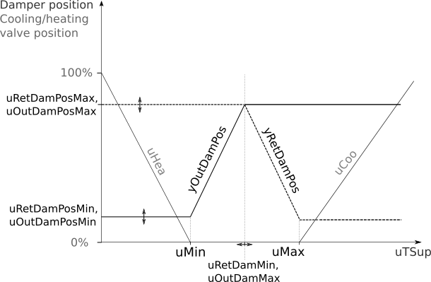
This is a multi zone VAV AHU economizer modulation block. It calculates the outdoor and return air damper positions based on the supply air temperature control loop signal. The implementation is in line with ASHRAE Guidline 36 (G36), PART 5.N.2.c. Damper positions are linearly mapped to the supply air control loop signal. This is a final sequence in the composite multi zone VAV AHU economizer control sequence. Damper position limits, which are the inputs to the sequence, are the outputs of Buildings.Obsolete.Controls.OBC.ASHRAE.G36_PR1.AHUs.MultiZone.VAV.Economizers.Subsequences.Limits and Buildings.Obsolete.Controls.OBC.ASHRAE.G36_PR1.AHUs.MultiZone.VAV.Economizers.Subsequences.Enable sequences.
When the economizer is enabled, the PI controller modulates the damper positions. Return and outdoor damper are not interlocked. When the economizer is disabled, the damper positions are set to the minimum outdoor air damper position limits.
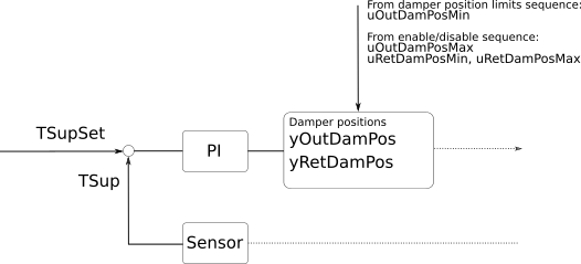
The control charts below show the input-output structure and an economizer damper modulation sequence assuming a well configured controller. Control diagram:
Multi zone AHU economizer modulation control chart:
Parameters
| Type | Name | Default | Description |
|---|---|---|---|
| Commissioning › Controller | |||
| Real | uMin | -0.25 | Lower limit of controller input when outdoor damper opens (see diagram) |
| Real | uMax | +0.25 | Upper limit of controller input when return damper is closed (see diagram) |
| Real | uOutDamMax | (uMin + uMax)/2 | Maximum loop signal for the OA damper to be fully open |
| Real | uRetDamMin | (uMin + uMax)/2 | Minimum loop signal for the RA damper to be fully open |
Connectors
| Type | Name | Default | Description |
|---|---|---|---|
| Buildings.Controls.OBC.CDL.Interfaces.RealInput | uTSup | Signal for supply air temperature control (T Sup Control Loop Signal in diagram) | |
| Buildings.Controls.OBC.CDL.Interfaces.RealInput | uOutDamPosMin | Minimum economizer damper position limit as returned by the damper position limits sequence | |
| Buildings.Controls.OBC.CDL.Interfaces.RealInput | uOutDamPosMax | Maximum economizer damper position limit as returned by the economizer enable-disable sequence. If the economizer is disabled, this value equals uOutDamPosMin | |
| Buildings.Controls.OBC.CDL.Interfaces.RealInput | uRetDamPosMin | Minimum return air damper position limit as returned by the economizer enable-disable sequence | |
| Buildings.Controls.OBC.CDL.Interfaces.RealInput | uRetDamPosMax | Maximum return air damper position limit as returned by the economizer enable-disable sequence | |
| Buildings.Controls.OBC.CDL.Interfaces.RealOutput | yOutDamPos | Economizer damper position | |
| Buildings.Controls.OBC.CDL.Interfaces.RealOutput | yRetDamPos | Return air damper position |
Revisions
-
April 24, 2021, by Michael Wetter:
Removed limit on time rate of change on damper signal. The dampers model has already a delay which should make them sufficiently slow. Adding this delay in the controller makes it harder to tune the controls. This change also removed the parametersamplePeriod. -
October 13, 2017, by Michael Wetter:
Corrected implementation for when dampers are such positioned that they prevent the mixed air temperature from being below the freezing set point. -
October 11, 2017, by Michael Wetter:
Corrected implementation to use control loop signal as input. -
September 29, 2017, by Michael Wetter:
Corrected implementation by adding reverse action. -
June 28, 2017, by Milica Grahovac:
First implementation.