blockDamperValves
Information
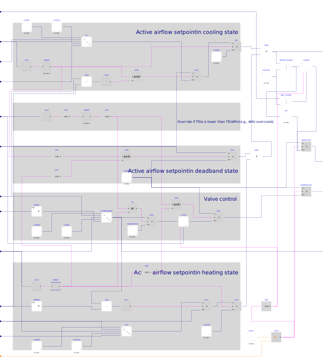
This sequence sets the damper and valve position for VAV reheat terminal unit. The implementation is according to ASHRAE Guideline 36 (G36), PART 5.E.6. The calculation is done following the steps below.
-
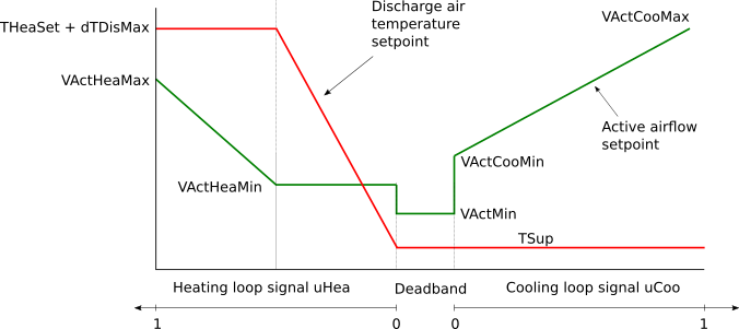
When the zone state is cooling (
uCoo>0), then the cooling loop outputuCooshall be mapped to the airflow setpoint from the cooling minimumVActCooMin_flowto the cooling maximumVActCooMax_flowairflow setpoints. The hot water valve is closed (yHeaVal=0) unless the discharge air temperatureTDisis below the minimum setpoint (10 °C). -
If supply air temperature
TSupfrom the AHU is greater than room temperatureTZon, cooling supply airflow setpoint shall be no higher than the minimum. -
When the zone state is Deadband (
uCoo=0anduHea=0), then the active airflow setpoint shall be the minimum airflow setpointVActMin_flow. Hot water valve is closed unless the discharge air temperature is below the minimum setpoint (10 °C). -
When the zone state is Heating (
uHea>0), then the heating loop shall maintain space temperature at the heating setpoint as follows:- From 0-50%, the heating loop output
uHeashall reset the discharge temperature setpoint from current AHU SAT setpointTSupto a maximum ofdTDisZonSetMaxabove space temperature setpoint. The airflow setpoint shall be the heating minimumVActHeaMin_flow. - From 50-100%, if the discharge air temperature
TDisis greater than room temperature plus 2.8 Kelvin, the heating loop outputuHeashall reset the airflow setpoint from the heating minimum airflow setpointVActHeaMin_flowto the heating maximum airflow setpointVActHeaMax_flow.
- From 0-50%, the heating loop output
-
The hot water valve (or modulating electric heating coil) shall be modulated to maintain the discharge temperature at setpoint.
-
The VAV damper shall be modulated by a control loop to maintain the measured airflow at the active setpoint.
The sequences of controlling damper and valve position for VAV reheat terminal unit are described in the following figure below.
Parameters
| Type | Name | Default | Description |
|---|---|---|---|
| Real | dTDisZonSetMax | 11 | Zone maximum discharge air temperature above heating setpoint |
| Real | TDisMin | 283.15 | Lowest discharge air temperature |
| Valve | |||
| Buildings.Controls.OBC.CDL.Types.SimpleController | controllerTypeVal | Buildings.Controls.OBC.CDL.Types.SimpleController.PI | Type of controller |
| Real | kVal | 0.5 | Gain of controller for valve control |
| Real | TiVal | 300 | Time constant of integrator block for valve control |
| Real | TdVal | 0.1 | Time constant of derivative block for valve control |
| Damper | |||
| Boolean | have_pressureIndependentDamper | true | True: the VAV damper is pressure independent (with built-in flow controller) |
| Buildings.Controls.OBC.CDL.Types.SimpleController | controllerTypeDam | Buildings.Controls.OBC.CDL.Types.SimpleController.PI | Type of controller |
| Real | kDam | 0.5 | Gain of controller for damper control |
| Real | TiDam | 300 | Time constant of integrator block for damper control |
| Real | TdDam | 0.1 | Time constant of derivative block for damper control |
| Real | V_flow_nominal | Nominal volume flow rate, used to normalize control error | |
Connectors
Components
| Type | Name | Default | Description |
|---|---|---|---|
| Buildings.Controls.OBC.CDL.Logical.Not | not1 | Logical not | |
| Buildings.Controls.OBC.CDL.Logical.Not | not2 | Logical not | |
| Buildings.Controls.OBC.CDL.Logical.Not | not4 | Logical not | |
| Buildings.Controls.OBC.CDL.Logical.And | and2 | Check if current zone state is deadband | |
| Buildings.Controls.OBC.CDL.Logical.And | and4 | Logical and | |
| Buildings.Controls.OBC.CDL.Reals.Line | lin | Active airflow setpoint for cooling | |
| Buildings.Controls.OBC.CDL.Reals.Line | conTDisHeaSet | Discharge air temperature for heating | |
| Buildings.Controls.OBC.CDL.Reals.Line | lin3 | Active airflow setpoint for heating | |
| Buildings.Controls.OBC.CDL.Reals.PIDWithReset | conVal | Hot water valve controller | |
| Buildings.Controls.OBC.CDL.Reals.PIDWithReset | conDam | Damper position controller | |
| Buildings.Controls.OBC.CDL.Reals.Switch | swi | Output active cooling airflow according to cooling control signal | |
| Buildings.Controls.OBC.CDL.Reals.Switch | swi1 | Output active airflow when it is in deadband state | |
| Buildings.Controls.OBC.CDL.Reals.Switch | swi2 | Acitive heating airflow rate | |
| Buildings.Controls.OBC.CDL.Reals.Switch | swi4 | Output active heating airflow according to heating control signal | |
| Buildings.Controls.OBC.CDL.Reals.Switch | swi5 | Output active cooling airflow |
Revisions
-
April 18, 2020, by Jianjun Hu:
Added option to check if the VAV damper is pressure independent.
This is for #1873. -
March 11, 2020, by Jianjun Hu:
Replaced multisum block with add blocks, replaced gain block used for normalization with division block.
This is for #1830. -
September 10, 2017, by Jianjun Hu:
First implementation.