
modelPartialParallel
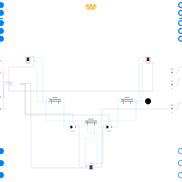
Partial ETS model with district heat exchanger and parallel connection of production systems
Extends from Buildings.DHC.ETS.BaseClasses.PartialETS (Partial class for modeling an energy transfer station).
Information
This is a base model providing the hydronic configuration for an energy transfer
station as described in the schematics below.
It is typically used to integrate systems providing both heating water and chilled
water, such as heat recovery chillers.
Furthermore, it can be connected to an adjustable number (nSouAmb)
of systems serving as ambient sources (including the district heat exchanger).
- The connection to the district loop is realized with a heat exchanger, according to the operating principles described in Buildings.DHC.ETS.Combined.Subsystems.HeatExchanger.
- The connection of the heating water and chilled water production systems to the systems serving as ambient sources is realized in parallel.
- A replaceable partial class is used to represent a supervisory controller, which must be replaced by a control block providing at least the control signals listed in Buildings.Obsolete.DHC.ETS.Combined.Controls.BaseClasses.PartialSupervisory.
Models that extend this base class must
-
specify the number of systems serving as ambient sources
nSouAmb, the number of heating water production systemsnSysHea, and the number of chilled water production systemsnSysCoo(by defaultnSysCoo=nSysHeawhich corresponds to a configuration where both productions are ensured by the same system, such as a heat recovery chiller), -
modify the parameter binding with the nominal mass flow rate of each connection
to each collector/distributor model, namely the parameter
mCon_flow_nominal(array) of the componentscolChiWat,colHeaWatandcolAmbWat. The connection index1for the componentscolChiWatandcolHeaWatis reserved for the connection with the ambient source circuit. It increases with the distance from the buffer tank. The connection index1for the componentcolAmbWatis reserved for the connection with the district heat exchanger. Note that the order of the connections has no impact on the flow distribution as the connections are in parallel.
Note that the model includes a pressure boundary condition which
is shared between the hot water and chilled water circuits, the two circuits
being hydronically connected.

Parameters
| Type | Name | Default | Description |
|---|---|---|---|
| Buildings.Fluid.Data.Fuels.Generic[nFue] | fue (from PartialETS) | Fuel type | |
| Buildings.DHC.ETS.Types.ConnectionConfiguration | conCon | Buildings.DHC.ETS.Types.ConnectionConfiguration.Pump | District connection configuration |
| Integer | nSysHea | Number of heating systems | |
| Integer | nSysCoo | nSysHea | Number of cooling systems |
| Integer | nSouAmb | 1 | Number of ambient sources |
| Configuration | |||
| TypDisSys | typ (from PartialETS) | Buildings.DHC.Types.DistrictSystemType.CombinedGeneration2to4 | Type of district system |
| Integer | nPorts_aHeaWat (from PartialETS) | 0 | Number of heating water return ports |
| Integer | nPorts_bHeaWat (from PartialETS) | 0 | Number of heating water supply ports |
| Integer | nPorts_aChiWat (from PartialETS) | 0 | Number of chilled water return ports |
| Integer | nPorts_bChiWat (from PartialETS) | 0 | Number of chilled water supply ports |
| Boolean | have_heaWat (from PartialETS) | false | Set to true if the ETS supplies heating water |
| Boolean | have_hotWat (from PartialETS) | false | Set to true if the ETS supplies hot water |
| Boolean | have_chiWat (from PartialETS) | false | Set to true if the ETS supplies chilled water |
| Boolean | have_fan (from PartialETS) | false | Set to true if fan power is computed |
| Boolean | have_pum (from PartialETS) | false | Set to true if pump power is computed |
| Boolean | have_eleHea (from PartialETS) | false | Set to true if the ETS has electric heating system |
| Integer | nFue (from PartialETS) | 0 | Number of fuel types (0 means no combustion system) |
| Boolean | have_eleCoo (from PartialETS) | false | Set to true if the ETS has electric cooling system |
| Boolean | have_weaBus (from PartialETS) | false | Set to true to use a weather bus |
| Assumptions | |||
| Boolean | allowFlowReversalSer (from PartialETS) | false | Set to true to allow flow reversal on service side |
| Boolean | allowFlowReversalBui (from PartialETS) | false | Set to true to allow flow reversal on building side |
| Nominal condition | |||
| Modelica.Units.SI.HeatFlowRate | QHeaWat_flow_nominal (from PartialETS) | 0 | Nominal capacity of heating system (>=0) |
| Modelica.Units.SI.HeatFlowRate | QHotWat_flow_nominal (from PartialETS) | 0 | Nominal capacity of hot water production system (>=0) |
| Modelica.Units.SI.HeatFlowRate | QChiWat_flow_nominal (from PartialETS) | 0 | Nominal capacity of cooling system (<=0) |
| Modelica.Units.SI.PressureDifference | dpValIso_nominal | 2E3 | Nominal pressure drop of ambient circuit isolation valves |
| District heat exchanger | |||
| Modelica.Units.SI.PressureDifference | dp1Hex_nominal | Nominal pressure drop across heat exchanger on district side | |
| Modelica.Units.SI.PressureDifference | dp2Hex_nominal | Nominal pressure drop across heat exchanger on building side | |
| Modelica.Units.SI.HeatFlowRate | QHex_flow_nominal | Nominal heat flow rate through heat exchanger (from district to building) | |
| Modelica.Units.SI.Temperature | T_a1Hex_nominal | Nominal water inlet temperature on district side | |
| Modelica.Units.SI.Temperature | T_b1Hex_nominal | Nominal water outlet temperature on district side | |
| Modelica.Units.SI.Temperature | T_a2Hex_nominal | Nominal water inlet temperature on building side | |
| Modelica.Units.SI.Temperature | T_b2Hex_nominal | Nominal water outlet temperature on building side | |
| Real | spePum1HexMin | 0.1 | Heat exchanger primary pump minimum speed (fractional) |
| Real | spePum2HexMin | 0.1 | Heat exchanger secondary pump minimum speed (fractional) |
| Buffer Tank | |||
| Modelica.Units.SI.Volume | VTanHeaWat | Heating water tank volume | |
| Modelica.Units.SI.Length | hTanHeaWat | (VTanHeaWat*16/Modelica.Constants.pi)^(1/3) | Heating water tank height (assuming twice the diameter) |
| Modelica.Units.SI.Length | dInsTanHeaWat | 0.1 | Heating water tank insulation thickness |
| Modelica.Units.SI.Volume | VTanChiWat | Chilled water tank volume | |
| Modelica.Units.SI.Length | hTanChiWat | (VTanChiWat*16/Modelica.Constants.pi)^(1/3) | Chilled water tank height (without insulation) |
| Modelica.Units.SI.Length | dInsTanChiWat | 0.1 | Chilled water tank insulation thickness |
| Integer | nSegTan | 3 | Number of volume segments for tanks |
Connectors
Components
Revisions
-
November 3, 2025, by Michael Wetter:
Moved toBuildings.Obsolete.
This is for #4354. -
July 14, 2021, by Antoine Gautier:
Added pressure boundary condition.
This is for issue #2561. -
December 21, 2020, by Antoine Gautier:
Added outputs for distributed energy flow rate. -
July 31, 2020, by Antoine Gautier:
First implementation.