modelHeatExchanger
District heat exchanger controller
Information
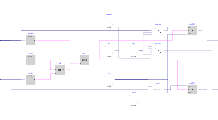
This block implements the control logic for the district heat exchanger, which realizes the interface between the building system and the district system.
The input signal u is yielded by the supervisory controller.
The primary and secondary circuits are enabled to operate if this input signal
is greater than zero and the return position of at least one isolation valve
is greater than 90%.
When enabled,
-
the secondary circuit is controlled based on the input signal
u, which is mapped to modulate in sequence the mixing valve (from full bypass to closed bypass for a control signal varying between 0% and 30%) and the pump speed (from the minimum to the maximum value for a control signal varying between 30% and 100%), and -
the primary pump speed (or valve opening) is directly modulated with
the input signal
u.
Note that the valve on the secondary side is needed to stabilize the control of the system when the secondary mass flow rate required to meet the heat or cold rejection demand is below the flow rate corresponding to the minimum pump speed.
Parameters
| Type | Name | Default | Description |
|---|---|---|---|
| Buildings.DHC.ETS.Types.ConnectionConfiguration | conCon | District connection configuration | |
| Real | spePum1Min | 0.1 | Heat exchanger primary pump minimum speed (fractional) |
| Real | spePum2Min | 0.1 | Heat exchanger secondary pump minimum speed (fractional) |
Connectors
| Type | Name | Default | Description |
|---|---|---|---|
| Buildings.Controls.OBC.CDL.Interfaces.RealInput[2] | yValIso | Isolation valves return position (index 1 for condenser) | |
| Buildings.Controls.OBC.CDL.Interfaces.RealOutput | y1 | District heat exchanger primary control signal | |
| Buildings.Controls.OBC.CDL.Interfaces.RealOutput | yPum2 | District heat exchanger secondary pump control signal | |
| Buildings.Controls.OBC.CDL.Interfaces.RealOutput | yVal2 | District heat exchanger secondary valve control signal | |
| Buildings.Controls.OBC.CDL.Interfaces.RealInput | u | Control signal for secondary side (from supervisory) |
Components
Revisions
-
November 14, 2025, by Michael Wetter:
Moved toBuildings.Obsolete.
This is for #4354. -
July 14, 2021, by Antoine Gautier:
Updated the control logic.
This is for issue #2561. -
July 31, 2020, by Antoine Gautier:
First implementation.