This tutorial gives step by step instructions on building and simulating a mixed convection model. The model tests the coupled simulation of Buildings.ThermalZones.Detailed.CFD with the FFD program by simulating ventilation with mixed convection in an empty room.
The temperature of the floor is fixed at 30°C and the temperature of the walls and the ceiling are fixed at 10°C. The supply air temperature is fixed at 10°C.
Figure (a) shows the schematic of the FFD simulation and Figure (b) shows the velocity vectors and temperatures on the X-Z plane at Y = 0.5 m as simulated by the FFD.
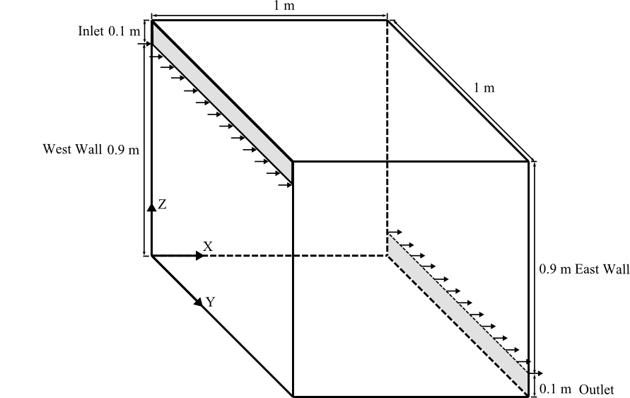
Figure (a)
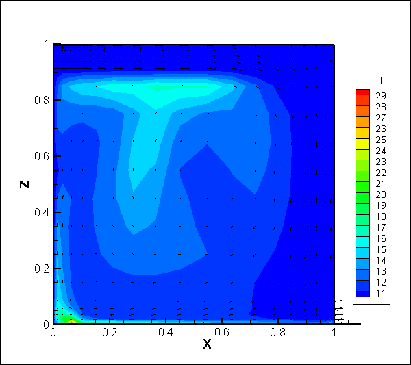
Figure (b)
This section describes step by step how to build and simulate the model.
Add the following model components into the
MixedConvection model:
roo.weaDat.qRadGai_flow,
qConGai_flow and qLatGai_flow,
respectively.multiple_x3.TFlo and
TOthWal respectively. Please note that it is necessary
to declare TOthWal as a vector of 5
elements.roo. Name it as
bouIn.roo is connected. Name it as bouOut.In the textual editor mode, add the medium and the number of surfaces as below:
package MediumA = Buildings.Media.GasesConstantDensity.MoistAirUnsaturated (T_default=283.15);
  parameter Integer nConExtWin=0;
  parameter Integer nConBou=0;
  parameter Integer nSurBou=6;
  parameter Integer nConExt=0;
  parameter Integer nConPar=0;
Edit roo as below:
Buildings.ThermalZones.Detailed.CFD roo(
  redeclare package Medium = MediumA,
  surBou(
    name={"East Wall","West Wall","North Wall","South Wall","Ceiling","Floor"},
    A={0.9,0.9,1,1,1,1},
    til={Buildings.Types.Tilt.Wall,
        Buildings.Types.Tilt.Wall,
        Buildings.Types.Tilt.Wall,
        Buildings.Types.Tilt.Wall,
        Buildings.Types.Tilt.Ceiling,
        Buildings.Types.Tilt.Floor},
    each absIR=1e-5,
    each absSol=1e-5,
    each boundaryCondition=Buildings.ThermalZones.Detailed.Types.CFDBoundaryConditions.Temperature),
    AFlo = 1*1,
    hRoo = 1,
    linearizeRadiation = false,
    useCFD = true,
    sensorName = {"Occupied zone air temperature", "Velocity"},
    cfdFilNam = "modelica://Buildings/Resources/Data/ThermalZones/Detailed/Examples/FFD/Tutorial/MixedConvection.ffd",
    nConExt = nConExt,
    nConExtWin = nConExtWin,
    nConPar = nConPar,
    nConBou = nConBou,
    nSurBou = nSurBou,
    nPorts = 2,
    portName={"Inlet","Outlet"},
    samplePeriod = 6);
Set the parameters for the following components:
qRadGai_flow, qConGai_flow and
qLatGai_flow to 0.TFlo to 303.15 Kelvin.TOthWal to 283.15 Kelvin.Set the values for the parameters of bouIn and
bouOut as below:
Fluid.Sources.MassFlowSource_T bouIn(
  redeclare package Medium = MediumA,
  nPorts=1,
  m_flow=0.1,
  T=283.15);
Fluid.Sources.FixedBoundary bouOut(
  redeclare package Medium = MediumA,
  nPorts=1);
Connect the components as shown in the figure below.
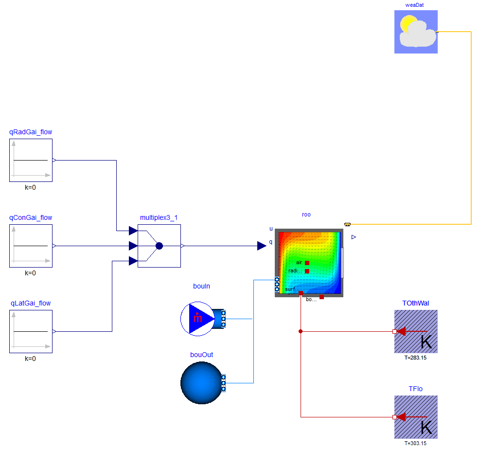
Confirm in the textual editor that the connections to
roo.ports are as follows:
connect(bouIn.ports[1], roo.ports[1]);
connect(bouOut.ports[1], roo.ports[2]);
Use the Simplified CFD Interface (SCI) to generate the input file for the FFD.
input.cfd (mesh file) and zeroone.dat
(obstacles file).MixedConvection.cfd and
MixedConvection.dat, respectively.Revise the FFD parameter input file
MixedConvection.ffd (an example file is available in
Buildings/Resources/Data/ThermalZones/Detailed/Examples/FFD/Tutorial/):
  inpu.parameter_file_format SCI
  inpu.parameter_file_name MixedConvection.cfd
  inpu.block_file_name MixedConvection.dat
  prob.nu 0.000015 // Kinematic viscosity
  prob.rho 1.205 // Density
  prob.gravx 0 // Gravity in x direction
  prob.gravy 0 // Gravity in y direction
  prob.gravz -9.81 // Gravity in z direction
  prob.cond 0.0257 // Conductivity
  prob.Cp 1006.0 // Specific heat capacity
  prob.beta 0.00343 // Thermal expansion coefficient
  prob.diff 0.00001 // Diffusivity for contaminants
  prob.coeff_h 0.0004 // Convective heat transfer coefficient near the wall
  prob.Temp_Buoyancy 10.0 // Reference temperature for calculating buoyance  force
  init.T 10.0 // Initial condition for Temperature
  init.u 0.0 // Initial condition for velocity u
  init.v 0.0 // Initial condition for velocity v
  init.w 0.0 // Initial condition for velocity w
MixedConvection.ffd,
MixedConvection.dat, and
MixedConvection.cfd in the directory
Buildings/Resources/Data/ThermalZones/Detailed/Examples/FFD/Tutorial/.180 seconds and choose, for example, the CVode
solver.Buildings/Resources/Image/Rooms/Examples/FFD/Tutorial/MixedConvection.mcr
that will generate the temperature contour and velocity vectors
shown in the Figure (b). Note: Tecplot is needed for this.| Name | Description |
|---|---|
|
|
Medium model |
lat as this is now
obtained from the weather data reader.