This is a duplicate model of Buildings.ThermalZones.Detailed.FLEXLAB.Rooms.X3A.TestCell with the wall separating X3A and X3B removed. It is designed for simulations where both X3A and X3B are used in the simulation to model the whole test bed. If a simulation is created using TestCell from both packages the dividing wall will be modeled twice, so one of the two models used must be created without the dividing wall in the model.
This documentation states only the items which are different from the Buildings.ThermalZones.Detailed.FLEXLAB.Rooms.X3A.TestCell model. For documentation on the rest of the walls and connections see that documentation instead.
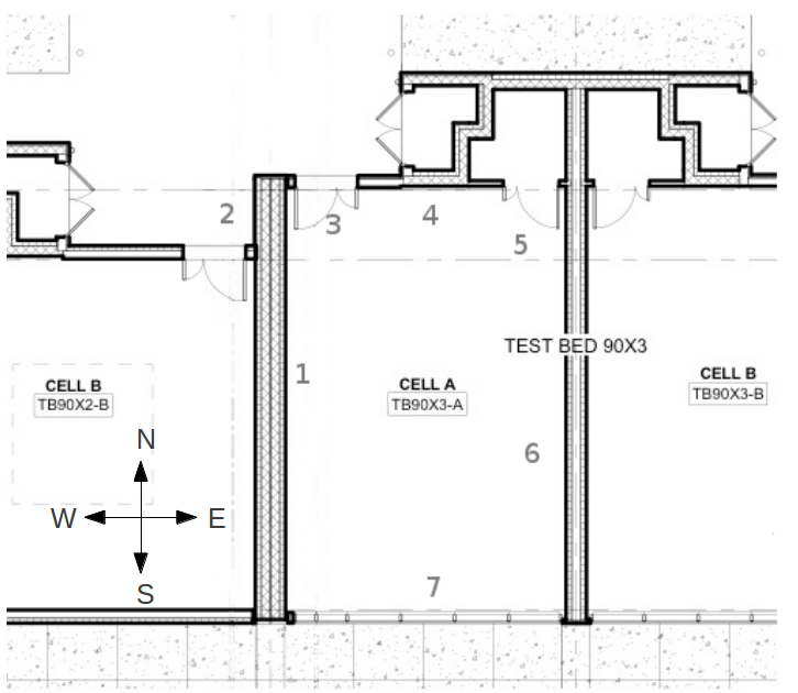
There are 7 different wall sections described in the model. They are shown in the figure below. This documentation only describes wall section 6.
The different wall sections are entered into the model according to the following table.
| Wall Section Number | Description | Location in Model | Corresponding Layer |
|---|---|---|---|
| 6 | This east wall connects to test cell X3B. This model contains an air gap instead of a model of the wall. It is intended to be connected to the wall model in X3B. | surBou[2] |
Because wall section 6 was moved from datConBou[2] to surBou[2] the reference for other constructions in datConBou have changed as well. These changes are documented in the following table.
| Wall Section Number | Physical Description | Location in TestCell | Location in TestCelNoDiv |
|---|---|---|---|
| 4 | Insulated wall separating the test cell and the electrical room | datConBou[5] | datConBou[4] |
| 5 | Partition wall and door separating the test cell and the closet | Wall: datConBou[3] Door: datConBou[4] |
Wall: datConBou[2] Door: datConBou[3] |
Several of the connections in this model are intended to be connected to specific surfaces in other room models. The following table describes the connections to models outside of the X3A package. The connections in datConExt are not described in the table because they are connected to the external environment, and no additional heat port connections are necessary. A rationale for why the model is created this way is also provided if it is considered necessary.
| Location in TestCell | Description of External Connection | Location in External Model | Rationale |
|---|---|---|---|
| surf_surBou[2] | Dividing wall modeled in ThermalZones.Detailed.FLEXLAB.Rooms.X3B.TestCell | X3B.TestCell.surf_conBou[1] | X3B.TestCell.surf_conBou[1] is the location of the cell dividing wall in the neighboring test cell. Connecting X3A.TestCellNoCelDiv.surf_surBou[2] to this port models heat transfer from the wall in ThermalZones.Detailed.FLEXLAB.Rooms.X3B.TestCell to the air in this space. |