This is a model for the electrical room connected to test cell 3B in the LBNL User Facility. Other models are provided for the main space of the test cell and the connected closet. This documentation describes the wall constructions used in the electrical room model. For documentation describing how the room models are to be connected to develop a model of the entire X3B test cell see Buildings.ThermalZones.Detailed.FLEXLAB.Rooms.X3B.
There are 4 different wall sections described in the model. They are shown in the figure below.
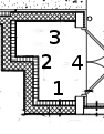
The different wall sections are entered into the model according to the following table.
| Wall Section Number | Description | Location in Model | Corresponding Layer |
|---|---|---|---|
| 1 | South air space connecting to TestCell | surBou[1] | |
| 2 | West air space connecting to Closet | surBou[2] | |
| 3 | North exterior wall | datConExt[1] | eleExt |
| 4 | East exterior door and wall | Wall: datConExt[2] Door: datConExt[3] |
Wall: eleExt Door: extDooUn |
There are two additional surfaces which are not included in the
diagram. One is the model of the roof. It is modeled in
datConExt[4] using the layer roo. The other is the
floor, which is modeled in datConBou[1] using the layer
slaCon.
Several of the connections in this model are intended to be connected to specific surfaces in other room models. The following table describes the connections to rooms which are not in the X3B package. The constructions in datConExt are not described in the table because they are connected to the external environment, and no additional heat port connections are necessary. A rationale for why the model is created this way is also provided if it is considered necessary.
| Location in Electrical | Description of External Connection | Rationale |
|---|---|---|
| surf_conBou[1] | Connection to ground temperature model | This port represents the bottom of the floor in the space. It is to be connected to a heat port representing the temperature of the ground. |