blockSupplyFan
Supply fan speed setpoint for single zone VAV system
Information
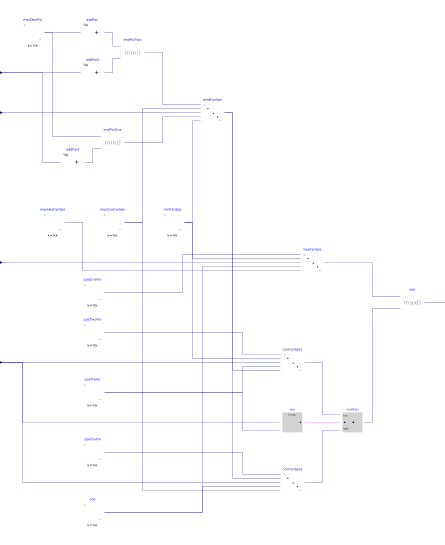
Block that outputs the set points for the fan speed for a single zone VAV system. The implementation is according to the Section 5.18.4 of ASHRAE Guideline 36, May 2020.
Fan speed setpoint
The supply fan shall run whenever the unit is in any mode other than unoccupied mode. Also, a ramp function should be applied to prevent changes in fan speed of more than 10% per minute.
Minimum, medium, and maximum fan speeds shall be as follows:
-
Minimum speed
minSpe, maximum cooling speedmaxCooSpe, and maximum heatng speedmaxHeaSpeshall be given per Section 3.2.2.1 of ASHRAE Guideline 36. -
Medium fan speed shall be reset linearly based on outdoor air temperature
TOutfromminSpewhen outdoor air temperature is greater than or equal to Endpoint 1 tomaxCooSpewhenTOutis less than or equal to Endpoint 2.-
Endpoint 1: the lesser of zone temperature
TZonplus 0.5 °C (1 °F) and maximum supply air dew pointTSupDew_max. -
Endpoint 2: the lesser of zone temperature
TZonminus 6 °C (10 °F) and maximum supply air dew pointTSupDew_maxminus 1 °C (2 °F).
-
Endpoint 1: the lesser of zone temperature
Control mapping
-
For a heating-loop signal
uHeaof 100% tospePoiOne(default 50%), fan speed is reset frommaxHeaSpetominSpe. -
For a heating-loop signal
uHeaofspePoiOneto 0%, fan speed set point isminSpe. -
In deadband (
uHea=0,uCoo=0), fan speed set point isminSpe. -
For a cooling-loop signal
uCooof 0% tospePoiTwo(default 25%), fan speed isminSpe. -
For a cooling-loop signal
uCooofspePoiTwotospePoiThr(default 50%), fan speed is reset fromminSpeto medium fan speed. -
For a cooling-loop signal
uCooofspePoiThrtospePoiFou(default 75%), fan speed is medium. -
For a cooling-loop signal of
uCoospePoiFouto 100%, fan speed is reset from medium tomaxCooSpe.
The figure below shows the sequence.

Note that the inputs uHea and uCoo must be computed
based on the same temperature sensors and control loops.
Parameters
| Type | Name | Default | Description |
|---|---|---|---|
| Temperatures | |||
| Real | TSupDew_max | Maximum supply air dew-point temperature. It's typically only needed in humid type “A” climates. A typical value is 17°C. For mild and dry climates, a high set point (e.g. 24°C) should be entered for maximum efficiency | |
| Speed | |||
| Real | maxHeaSpe | Maximum fan speed for heating | |
| Real | maxCooSpe | Maximum fan speed for cooling | |
| Real | minSpe | Minimum fan speed | |
| Advanced › Speed | |||
| Real | spePoiOne | 0.5 | Point 1 on x-axis of control map for speed control, when it is in heating state |
| Real | spePoiTwo | 0.25 | Point 2 on x-axis of control map for speed control, when it is in cooling state |
| Real | spePoiThr | 0.5 | Point 3 on x-axis of control map for speed control, when it is in cooling state |
| Real | spePoiFou | 0.75 | Point 4 on x-axis of control map for speed control, when it is in cooling state |
Connectors
| Type | Name | Default | Description |
|---|---|---|---|
| Buildings.Controls.OBC.CDL.Interfaces.RealInput | TZon | Zone temperature | |
| Buildings.Controls.OBC.CDL.Interfaces.RealInput | TOut | Outdoor air temperature | |
| Buildings.Controls.OBC.CDL.Interfaces.RealInput | uHea | Heating control signal | |
| Buildings.Controls.OBC.CDL.Interfaces.RealInput | uCoo | Cooling control signal | |
| Buildings.Controls.OBC.CDL.Interfaces.RealOutput | y | Fan speed |
Revisions
-
June 30, 2025, by Jianjun Hu:
First implementation.