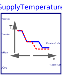
blockSupplyTemperature
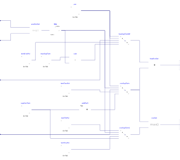
Information
Block that outputs the set points for the supply air temperature for cooling, heating and economizer control for a single zone VAV system. The implementation is according to the Section 5.18.4 of ASHRAE Guideline 36, May 2020.
Supply temperature setpoints
The output TSupCooSet is to be used to control the cooling coil,
and the output
TSupHeaEcoSet is to be used to control the heating coil and the
economizer dampers.
When it is in deadband state, the output TSupCooSet and TSupHeaEcoSet
shall be average of the zone heating setpoint THeaSet and the zone
cooling setpoint TCooSet but shall be no lower than TSupDea_min,
21 °C (70 °F),
and no higher than TSupDea_max, 24 °C (75 °F),
Control mapping
-
For a heating-loop signal
uHeaof 100% totemPoiOne(default 50%),TSupHeaEcoSetshould beTSup_max. -
For a heating-loop signal
uHeaoftemPoiOneto 0%,TSupHeaEcoSetis reset fromTSup_maxto the deadband value. -
In deadband (
uHea=0,uCoo=0),TSupHeaEcoSetis the deadband value. -
For a cooling-loop signal
uCooof 0% totemPoiTwo(default 25%),TSupHeaEcoSetis reset from deadband value toTSup_minminus 1 °C (2 °F), whileTSupCooSetis the deadband value. -
For a cooling-loop signal
uCoooftemPoiTwototemPoiThr(default 50%),TSupHeaEcoSetandTSupCooSetare unchanged. -
For a cooling-loop signal
uCoooftemPoiThrtotemPoiFou(default 75%),TSupHeaEcoSetremains atTSup_minminus 1 °C (2 °F), whileTSupCooSetis reset from the deadband value toTSup_min. -
For a cooling-loop signal
uCoooftemPoiFouto 100%,TSupHeaEcoSetandTSupCooSetare unchanged.
The figure below shows the sequence.

Note that the inputs uHea and uCoo must be computed
based on the same temperature sensors and control loops.
Parameters
| Type | Name | Default | Description |
|---|---|---|---|
| Temperatures | |||
| Real | TSup_max | Maximum supply air temperature for heating | |
| Real | TSup_min | Minimum supply air temperature for cooling | |
| Real | TSupDea_min | 294.15 | Minimum supply temperature when it is in deadband state |
| Real | TSupDea_max | 297.15 | Maximum supply temperature when it is in deadband state |
| Advanced › Temperatures | |||
| Real | temPoiOne | 0.5 | Point 1 on x-axis of control map for temperature control, when it is in heating state |
| Real | temPoiTwo | 0.25 | Point 2 on x-axis of control map for temperature control, when it is in cooling state |
| Real | temPoiThr | 0.5 | Point 3 on x-axis of control map for temperature control, when it is in cooling state |
| Real | temPoiFou | 0.75 | Point 4 on x-axis of control map for temperature control, when it is in cooling state |
Connectors
| Type | Name | Default | Description |
|---|---|---|---|
| Buildings.Controls.OBC.CDL.Interfaces.RealInput | uHea | Heating control signal | |
| Buildings.Controls.OBC.CDL.Interfaces.RealInput | uCoo | Cooling control signal | |
| Buildings.Controls.OBC.CDL.Interfaces.RealInput | TCooSet | Cooling setpoints for zone temperature | |
| Buildings.Controls.OBC.CDL.Interfaces.RealInput | THeaSet | Heating setpoints for zone temperature | |
| Buildings.Controls.OBC.CDL.Interfaces.RealOutput | TSupHeaEcoSet | Temperature setpoint for heating coil and for economizer | |
| Buildings.Controls.OBC.CDL.Interfaces.RealOutput | TSupCooSet | Cooling supply air temperature setpoint |
Revisions
-
June 30, 2025, by Jianjun Hu:
First implementation.