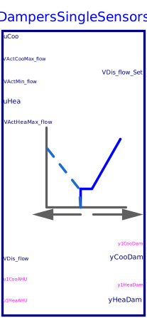
blockDampersSingleSensors
Output signals for controlling dampers of snap-acting controlled dual-duct terminal unit with single discharge airflow sensors
Information
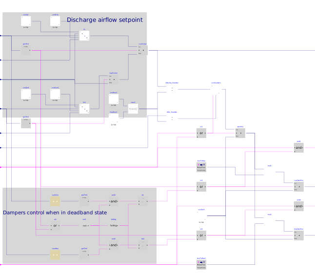
This sequence sets the dampers for snap-acting controlled dual-duct terminal unit with single discharge airflow sensors. The implementation is according to Section 5.11.5.2 of ASHRAE Guideline 36, May 2020. The calculation is done following the steps below.
-
When the zone state is cooling (
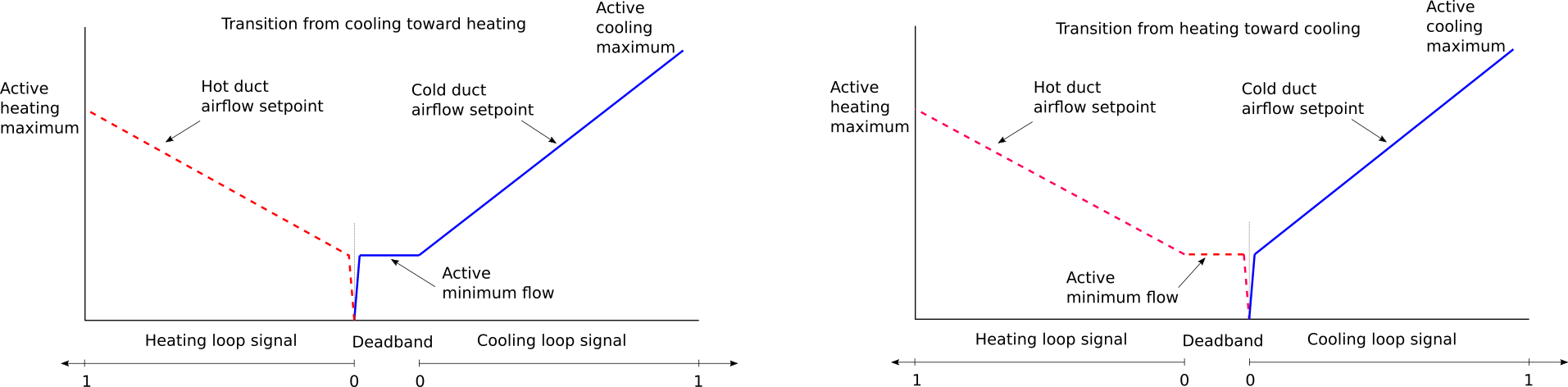
uCoo > 0), then the cooling loop outputuCooshall reset the discharge airflow setpointVDis_flow_Setfrom the minimumVActMin_flowto cooling maximum setpointVActCooMax_flow. The cooling damper shall be modulated by a control loop to maintain the measured discharge aiflowVDis_flowat setpoint. The heating damper shall be closedyHeaDam=0. -
When the zone state is deadband (
uCoo=0anduHea=0), the discharge airflow set pointVDis_flow_Setshall be the zone minimumVActMin_flow, maintained by the damper that was operative just before entering deadband. The other damper shall remain closed. In other words, when going from cooling to deadband, the cooling damper shall maintain the discharge airflow at the zone minimum set point, and the heating damper shall be closed. When going from heating to deadband, the heating damper shall maintain the discharge airflow at the zone minimum set point, and the cooling damper shall be closed. -
When the zone state is heating (
uHea > 0), then the heating loop outputuHeashall reset the discharge airflow setpointVDis_flow_Setfrom the minimumVActMin_flowto heating maximum setpointVActHeaMax_flow. The heating damper shall be modulated by a control loop to maintain the measured discharge aiflowVDis_flowat setpoint. The cooling damper shall be closedyCooDam=0. -
Overriding above controls:
-
If heating air handler is not proven ON (
u1HeaAHU=false), the heating damper shall be closed (yHeaDam=0). -
If cooling air handler is not proven ON (
u1CooAHU=false), the cooling damper shall be closed (yCooDam=0).
-
If heating air handler is not proven ON (
The sequences of controlling dampers position for snap-acting controlled dual-duct terminal unit with single discharge airflow sensors are described in the following figure below.
Parameters
| Type | Name | Default | Description |
|---|---|---|---|
| Real | VCooMax_flow | Design zone cooling maximum airflow rate | |
| Real | VHeaMax_flow | Design zone heating maximum airflow rate | |
| Buildings.Controls.OBC.CDL.Types.SimpleController | controllerTypeDam | Buildings.Controls.OBC.CDL.Types.SimpleController.PI | Type of controller |
| Real | kDam | 0.5 | Gain of controller for damper control |
| Real | TiDam | 300 | Time constant of integrator block for damper control |
| Real | TdDam | 0.1 | Time constant of derivative block for damper control |
| Advanced | |||
| Real | samplePeriod | Sample period of component | |
| Real | looHys | 0.05 | Loop output hysteresis below which the output will be seen as zero |
| Real | iniDam | 0.01 | Initial damper position when the damper control is enabled |
Connectors
Components
Revisions
-
January 12, 2023, by Jianjun Hu:
Removed the parameterhave_preIndDamto exclude the option of using pressure independant damper.
This is for issue 3139. -
August 1, 2020, by Jianjun Hu:
First implementation.