blockController

Information
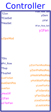
Controller for variable-volume parallel fan-powered terminal unit according to Section 5.8 of ASHRAE
Guideline 36, May 2020. It outputs discharge airflow setpoint VSet_flow_Set,
damper position setpoint yDam, hot water valve position setpoint
yVal, terminal fan command on status y1Fan and
the airflow setpoint VFan_flow_Set, AHU cooling supply temperature
setpoint reset request yZonTemResReq, and static pressure setpoint
reset request yZonPreResReq, hot water reset request yHeaValResReq
and yHotWatPlaReq. It also outputs the alarms about the low airflow
yLowFloAla, low discharge temperature yLowTemAla,
leaking damper yLeaDamAla and valve yLeaValAla,
airflow sensor calibration alarm yFloSenAla and the terminal fan status alarm
yFanStaAla.
The sequence consists of six subsequences.
a. Heating and cooling control loop
The subsequence is implementd according to Section 5.3.4. The measured zone
temperature TZon, zone setpoints temperatures THeaSet and
TCooSet are inputs to the instance of class
Buildings.Controls.OBC.ASHRAE.G36.ThermalZones.ZoneStates to generate the
heating and cooling control loop signal.
b. Active airflow setpoint calculation
This sequence sets the active cooling maximum and minimum airflow according to
Section 5.8.4. Depending on operation modes uOpeMod, it sets the
airflow rate limits.
See
Buildings.Controls.OBC.ASHRAE.G36.TerminalUnits.ParallelFanVVF.Subsequences.ActiveAirFlow.
c. Damper and valve control
This sequence sets the damper and valve position setpoints for the terminal unit.
It also sets the command on status of the terminal fan and the airflow setpoint.
The implementation is according to Section 5.8.5. According to heating and cooling
control loop signal, it calculates the discharge air temperature setpoint
TDisSet. Along with the active cooling maximum and minimum airflow setpoint, measured
zone temperature, the sequence outputs yDam, yVal,
TDisSet and discharge airflow rate setpoint VDis_flow_Set.
See
Buildings.Controls.OBC.ASHRAE.G36.TerminalUnits.ParallelFanVVF.Subsequences.DamperValves.
d. System reset requests generation
According to Section 5.8.8, this sequence outputs the system reset requests, i.e.
cooling supply air temperature reset requests yZonTemResReq,
static pressure reset requests yZonPreResReq, hot water reset
requests yHeaValResReq, and the hot water plant reset requests
yHotWatPlaReq.
See
Buildings.Controls.OBC.ASHRAE.G36.TerminalUnits.ParallelFanVVF.Subsequences.SystemRequests.
e. Alarms
According to Section 5.8.6, this sequence outputs the alarms of low discharge flow, low discharge temperature, fan status alarm, leaking damper, leaking valve, and airflow sensor calibration alarm. See Buildings.Controls.OBC.ASHRAE.G36.TerminalUnits.ParallelFanVVF.Subsequences.Alarms.
f. Testing and commissioning overrides
According to Section 5.8.7, this sequence allows the override the aiflow setpoints, damper and valve position setpoints, terminal fan command. See Buildings.Controls.OBC.ASHRAE.G36.TerminalUnits.ParallelFanVVF.Subsequences.Overrides.
Parameters
| Type | Name | Default | Description |
|---|---|---|---|
| Buildings.Controls.OBC.ASHRAE.G36.Types.VentilationStandard | venStd | Ventilation standard, ASHRAE 62.1 or Title 24 | |
| Boolean | have_winSen | true | True: the zone has window sensor |
| Boolean | have_occSen | true | True: the zone has occupancy sensor |
| Boolean | have_CO2Sen | true | True: the zone has CO2 sensor |
| Buildings.Controls.OBC.ASHRAE.G36.Types.HeatingCoil | heaCoi | Buildings.Controls.OBC.ASHRAE.G36.Types.HeatingCoil.WaterBased | Heating coil type |
| Boolean | permit_occStandby | true | True: occupied-standby mode is permitted |
| Real | VOccMin_flow | Zone minimum outdoor airflow for occupants | |
| Real | VAreMin_flow | Zone minimum outdoor airflow for building area | |
| Design conditions | |||
| Real | VAreBreZon_flow | Design area component of the breathing zone outdoor airflow | |
| Real | VPopBreZon_flow | Design population component of the breathing zone outdoor airflow | |
| Real | VMin_flow | Design zone minimum airflow setpoint | |
| Real | VCooMax_flow | Design zone cooling maximum airflow rate | |
| Control loops › Cooling | |||
| Real | kCooCon | 0.1 | Gain of controller for cooling control loop |
| Real | TiCooCon | 900 | Time constant of integrator block for cooling control loop |
| Control loops › Heating | |||
| Real | kHeaCon | 0.1 | Gain of controller for heating control loop |
| Real | TiHeaCon | 900 | Time constant of integrator block for heating control loop |
| Damper and valve control | |||
| Real | dTDisZonSetMax | 11 | Zone maximum discharge air temperature above heating setpoint |
| Real | minRat | Lowest parallel fan rate when it receives the lowest signal from BAS | |
| Real | maxRat | Maximum heating-fan airflow setpoint | |
| Damper and valve control › Valve | |||
| CDL.Types.SimpleController | controllerTypeVal | Buildings.Controls.OBC.CDL.Types.SimpleController.PI | Type of controller |
| Real | kVal | 0.5 | Gain of controller for valve control |
| Real | TiVal | 300 | Time constant of integrator block for valve control |
| Real | TdVal | 0.1 | Time constant of derivative block for valve control |
| Damper and valve control › Damper | |||
| CDL.Types.SimpleController | controllerTypeDam | Buildings.Controls.OBC.CDL.Types.SimpleController.PI | Type of controller |
| Real | kDam | 0.5 | Gain of controller for damper control |
| Real | TiDam | 300 | Time constant of integrator block for damper control |
| Real | TdDam | 0.1 | Time constant of derivative block for damper control |
| System requests | |||
| Real | thrTemDif | 3 | Threshold difference between zone temperature and cooling setpoint for generating 3 cooling SAT reset requests |
| Real | twoTemDif | 2 | Threshold difference between zone temperature and cooling setpoint for generating 2 cooling SAT reset requests |
| Real | thrTDis_1 | 17 | Threshold difference between discharge air temperature and its setpoint for generating 3 hot water reset requests |
| Real | thrTDis_2 | 8.3 | Threshold difference between discharge air temperature and its setpoint for generating 2 hot water reset requests |
| System requests › Duration time | |||
| Real | durTimTem | 120 | Duration time of zone temperature exceeds setpoint |
| Real | durTimFlo | 60 | Duration time of airflow rate less than setpoint |
| Real | durTimDisAir | 300 | Duration time of discharge air temperature less than setpoint |
| Alarms | |||
| Real | staPreMul | 1 | Importance multiplier for the zone static pressure reset control loop |
| Real | hotWatRes | 1 | Importance multiplier for the hot water reset control loop |
| Real | lowFloTim | 300 | Threshold time to check low flow rate |
| Real | lowTemTim | 600 | Threshold time to check low discharge temperature |
| Real | comChaTim | 15 | Threshold time after fan command change |
| Real | fanOffTim | 600 | Threshold time to check fan off |
| Real | leaFloTim | 600 | Threshold time to check damper leaking airflow |
| Real | valCloTim | 900 | Threshold time to check valve leaking water flow |
| Time-based suppresion | |||
| Real | samplePeriod | 120 | Sample period of component, set to the same value as the trim and respond that process static pressure reset |
| Real | chaRat | 540 | Gain factor to calculate suppression time based on the change of the setpoint, seconds per Kelvin |
| Real | maxSupTim | 1800 | Maximum suppression time |
| Advanced | |||
| Real | dTHys | 0.25 | Near zero temperature difference, below which the difference will be seen as zero |
| Real | looHys | 0.01 | Loop output hysteresis below which the output will be seen as zero |
| Real | floHys | 0.01*VMin_flow | Near zero flow rate, below which the flow rate or difference will be seen as zero |
| Real | damPosHys | 0.005 | Near zero damper position, below which the damper will be seen as closed |
| Real | valPosHys | 0.005 | Near zero valve position, below which the valve will be seen as closed |
| Real | staTim | 1800 | Delay triggering alarms after enabling AHU supply fan |
| Real | iniDam | 0.01 | Initial damper position when the damper control is enabled |
| Advanced › Control loops | |||
| Real | timChe | 30 | Threshold time to check the zone temperature status |
| Advanced › Distribution effectiveness | |||
| Real | zonDisEff_cool | 1.0 | Zone cooling air distribution effectiveness |
| Real | zonDisEff_heat | 0.8 | Zone heating air distribution effectiveness |
Connectors
| Type | Name | Default | Description |
|---|---|---|---|
| Buildings.Controls.OBC.CDL.Interfaces.RealInput | TZon | Measured room temperature | |
| Buildings.Controls.OBC.CDL.Interfaces.RealInput | TCooSet | Setpoint temperature for room for cooling | |
| Buildings.Controls.OBC.CDL.Interfaces.RealInput | THeaSet | Setpoint temperature for room for heating | |
| Buildings.Controls.OBC.CDL.Interfaces.BooleanInput | u1Win | Window status, normally closed (true), when windows open, it becomes false | |
| Buildings.Controls.OBC.CDL.Interfaces.BooleanInput | u1Occ | True: the zone is populated | |
| Buildings.Controls.OBC.CDL.Interfaces.IntegerInput | uOpeMod | Zone operation mode | |
| Buildings.Controls.OBC.CDL.Interfaces.RealInput | ppmCO2Set | CO2 concentration setpoint | |
| Buildings.Controls.OBC.CDL.Interfaces.RealInput | ppmCO2 | Detected CO2 concentration | |
| Buildings.Controls.OBC.CDL.Interfaces.RealInput | VParFan_flow | Parallel fan airflow rate | |
| Buildings.Controls.OBC.CDL.Interfaces.RealInput | TDis | Measured supply air temperature after heating coil | |
| Buildings.Controls.OBC.CDL.Interfaces.RealInput | VPri_flow | Measured primary airflow rate airflow rate | |
| Buildings.Controls.OBC.CDL.Interfaces.RealInput | TSup | Temperature of the air supplied from central air handler | |
| Buildings.Controls.OBC.CDL.Interfaces.RealInput | TSupSet | Supply air temperature setpoint from central air handler | |
| Buildings.Controls.OBC.CDL.Interfaces.IntegerInput | oveFloSet | Index of overriding flow setpoint, 1: set to zero; 2: set to cooling maximum; 3: set to minimum flow; 4: set to heating maximum | |
| Buildings.Controls.OBC.CDL.Interfaces.IntegerInput | oveDamPos | Index of overriding damper position, 1: set to close; 2: set to open | |
| Buildings.Controls.OBC.CDL.Interfaces.IntegerInput | oveFan | Index of overriding terminal fan status, 1: turn fan off; 2: turn fan on | |
| Buildings.Controls.OBC.CDL.Interfaces.BooleanInput | uHeaOff | Override heating valve position, true: close heating valve | |
| Buildings.Controls.OBC.CDL.Interfaces.BooleanInput | u1Fan | AHU supply fan status | |
| Buildings.Controls.OBC.CDL.Interfaces.BooleanInput | u1TerFan | Terminal fan status | |
| Buildings.Controls.OBC.CDL.Interfaces.BooleanInput | u1HotPla | Hot water plant status | |
| Buildings.Controls.OBC.CDL.Interfaces.RealOutput | VSet_flow | Discharge airflow setpoint after considering override | |
| Buildings.Controls.OBC.CDL.Interfaces.RealOutput | yDam | Damper commanded position, or commanded flow rate ratio | |
| Buildings.Controls.OBC.CDL.Interfaces.RealOutput | yVal | Heating valve commanded position | |
| Buildings.Controls.OBC.CDL.Interfaces.RealOutput | VFan_flow_Set | Paralle fan flow rate setpoint | |
| Buildings.Controls.OBC.CDL.Interfaces.BooleanOutput | y1Fan | Terminal fan command on status | |
| Buildings.Controls.OBC.CDL.Interfaces.RealOutput | VAdjPopBreZon_flow | Adjusted population component breathing zone flow rate | |
| Buildings.Controls.OBC.CDL.Interfaces.RealOutput | VAdjAreBreZon_flow | Adjusted area component breathing zone flow rate | |
| Buildings.Controls.OBC.CDL.Interfaces.RealOutput | VMinOA_flow | Minimum outdoor airflow setpoint | |
| Buildings.Controls.OBC.CDL.Interfaces.RealOutput | VZonAbsMin_flow | Zone absolute minimum outdoor airflow setpoint | |
| Buildings.Controls.OBC.CDL.Interfaces.RealOutput | VZonDesMin_flow | Zone design minimum outdoor airflow setpoint | |
| Buildings.Controls.OBC.CDL.Interfaces.RealOutput | yCO2 | CO2 control loop signal | |
| Buildings.Controls.OBC.CDL.Interfaces.IntegerOutput | yZonTemResReq | Zone cooling supply air temperature reset request | |
| Buildings.Controls.OBC.CDL.Interfaces.IntegerOutput | yZonPreResReq | Zone static pressure reset requests | |
| Buildings.Controls.OBC.CDL.Interfaces.IntegerOutput | yHeaValResReq | Hot water reset requests | |
| Buildings.Controls.OBC.CDL.Interfaces.IntegerOutput | yHotWatPlaReq | Request to heating hot-water plant | |
| Buildings.Controls.OBC.CDL.Interfaces.IntegerOutput | yLowFloAla | Low airflow alarms | |
| Buildings.Controls.OBC.CDL.Interfaces.IntegerOutput | yFloSenAla | Airflow sensor calibration alarm | |
| Buildings.Controls.OBC.CDL.Interfaces.IntegerOutput | yFanStaAla | Terminal fan status alarm | |
| Buildings.Controls.OBC.CDL.Interfaces.IntegerOutput | yLeaDamAla | Leaking damper alarm | |
| Buildings.Controls.OBC.CDL.Interfaces.IntegerOutput | yLeaValAla | Leaking valve alarm | |
| Buildings.Controls.OBC.CDL.Interfaces.IntegerOutput | yLowTemAla | Low discharge air temperature alarms |
Components
Revisions
-
January 12, 2023, by Jianjun Hu:
Removed the parameterhave_preIndDamto exclude the option of using pressure independant damper.
This is for issue 3139. -
August 1, 2020, by Jianjun Hu:
First implementation.