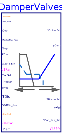
blockDamperValves
Output signals for controlling variable-volume series fan-powered terminal unit

Information
This sequence sets the series fan flow rate setpoint, damper and valve position for variable-volume series fan-powered terminal unit. The implementation is according to Section 5.10.5 of ASHRAE Guideline 36, May 2020. The calculation is done following the steps below.
-
When the zone state is cooling (
uCoo > 0), then the cooling loop outputuCooshall be mapped to the primary airflow setpoint from the minimumVActMin_flowto the cooling maximumVActCooMax_flowairflow setpoints. The heating coil is disabled (yVal=0).-
If supply air temperature
TSupfrom the AHU is greater than room temperatureTZon, cooling supply airflow setpoint shall be no higher than the minimum.
-
If supply air temperature
-
When the zone state is Deadband (
uCoo=0anduHea=0), then the primary airflow setpoint shall be the minimum airflow setpointVActMin_flow. The heating coil is disabled (yVal=0). -
When the zone state is Heating (
uHea > 0),-
As the heating-loop output
uHeaincreases from 0% to 50%, it shall reset the discharge temperatureTHeaDisSetfrom the current AHU setpoint temperatureTSupSetto a maximum ofdTDisZonSetMaxabove space temperature setpoint. -
The primary airflow setpoint shall be the minimum flow
VActMin_flow. - The heating coil shall be modulated to maintain the discharge temperature at setpoint.
-
As the heating-loop output
- The VAV damper shall be modulated by a control loop to maintain the measured primary airflow at the setpoint.
-
Fan control
-
Fan shall run whenever zone state is heating or cooling state, or if the associated
zone group is in occupied mode. Prior to starting fan, the damper is first driven
fully closed to ensure that the fan is not rotating backward. Once the fan is
proven on (
u1Fan=true) for a fixed time delay (15 seconds), the damper override is released. -
When the zone stats is cooling (
uCoo > 0), the series fan airflow setpoint shall be the larger ofVOAMin_flowand theVPri_flow_Set. If supply air temperatureTSupfrom the AHU is greater than room temperatureTZon, the series fan airflow setpoint shall be no higher thanVOAMin_flow. -
When the zone state is Deadband (
uCoo=0anduHea=0), the series fan airflow setpoint shall be equal toVOAMin_flow. -
When the zone state is Heating (
uHea > 0), as the heating-loop outputuHeaincreases from 50% to 100%, it shall reset the series fan airflow setpoint fromVOAMin_flowto the maximum heating-fan airflow setpointmaxRat.
-
Fan shall run whenever zone state is heating or cooling state, or if the associated
zone group is in occupied mode. Prior to starting fan, the damper is first driven
fully closed to ensure that the fan is not rotating backward. Once the fan is
proven on (
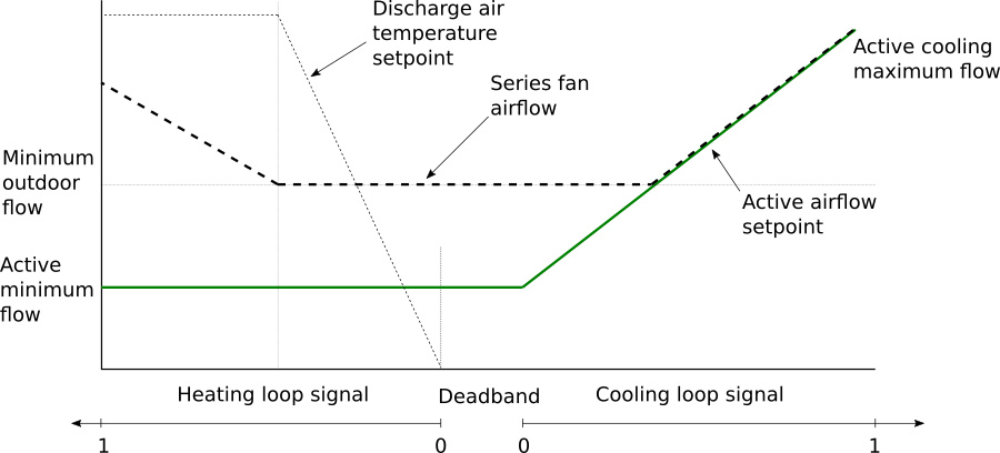
The sequences of controlling fan, damper position for variable-volume series fan-powered terminal unit are described in the following figure below.
As specified in Section 5.10.7 of ASHRAE Guideline 36, the airflow setpoint could be override by providing software switches that interlock to a system-level point to:
-
when
oveFloSetequals to 1, force the zone airflow setpointVPri_flow_Setto zero, -
when
oveFloSetequals to 2, force the zone airflow setpointVPri_flow_Setto zone cooling maximum airflow rateVCooMax_flow, -
when
oveFloSetequals to 3, force the zone airflow setpointVPri_flow_Setto zone minimum airflow setpointVMin_flow.
Parameters
| Type | Name | Default | Description |
|---|---|---|---|
| Real | dTDisZonSetMax | 11 | Zone maximum discharge air temperature above heating setpoint |
| Real | maxRat | Maximum heating-fan airflow setpoint | |
| Real | VMin_flow | Design zone minimum airflow setpoint | |
| Real | VCooMax_flow | Design zone cooling maximum airflow rate | |
| Valve | |||
| Buildings.Controls.OBC.CDL.Types.SimpleController | controllerTypeVal | Buildings.Controls.OBC.CDL.Types.SimpleController.PI | Type of controller |
| Real | kVal | 0.5 | Gain of controller for valve control |
| Real | TiVal | 300 | Time constant of integrator block for valve control |
| Real | TdVal | 0.1 | Time constant of derivative block for valve control |
| Damper | |||
| Buildings.Controls.OBC.CDL.Types.SimpleController | controllerTypeDam | Buildings.Controls.OBC.CDL.Types.SimpleController.PI | Type of controller |
| Real | kDam | 0.5 | Gain of controller for damper control |
| Real | TiDam | 300 | Time constant of integrator block for damper control |
| Real | TdDam | 0.1 | Time constant of derivative block for damper control |
| Advanced | |||
| Real | dTHys | 0.25 | Temperature difference hysteresis below which the temperature difference will be seen as zero |
| Real | looHys | 0.05 | Loop output hysteresis below which the output will be seen as zero |
| Real | floHys | 0.01 | Hysteresis for checking airflow rate |
| Real | damPosHys | 0.05 | Hysteresis for checking damper position |
| Real | iniDam | 0.01 | Initial damper position when the damper control is enabled |
Connectors
Revisions
-
August 24, 2023, by Jianjun Hu:
Added AHU supply fan status for damper position reset.
This is for issue 3257. -
January 12, 2023, by Jianjun Hu:
Removed the parameterhave_preIndDamto exclude the option of using pressure independant damper.
This is for issue 3139. -
August 1, 2020, by Jianjun Hu:
First implementation.