blockPIDWithInputGains
Information
PID controller in the standard form
yu = k/r (e(t) + 1 ⁄ Ti ∫ e(τ) dτ + Td d⁄dt e(t)),
with output reset, where yu is the control signal before output limitation, e(t) = us(t) - um(t) is the control error, with us being the set point and um being the measured quantity, k is the gain, Ti is the time constant of the integral term, Td is the time constant of the derivative term, r is a scaling factor, with default r=1. The scaling factor should be set to the typical order of magnitude of the range of the error e. For example, you may set r=100 to r=1000 if the control input is a pressure of a heating water circulation pump in units of Pascal, or leave r=1 if the control input is a room temperature.
Note that the units of k are the inverse of the units of the control error, while the units of Ti and Td are seconds.
The actual control output is
y = min( ymax, max( ymin, y)),
where ymin and ymax are limits for the control signal.
This block is identical to Buildings.Controls.OBC.CDL.Reals.PIDWithReset, except that the controller gains k, Ti and Td are inputs rather than parameters.
P, PI, PD, or PID action
Through the parameter controllerType, the controller can be configured
as P, PI, PD or PID controller. The default configuration is PI.
Reverse or direct action
Through the parameter reverseActing, the controller can be configured to
be reverse or direct acting.
The above standard form is reverse acting, which is the default configuration.
For a reverse acting controller, for a constant set point,
an increase in measurement signal u_m decreases the control output signal y
(Montgomery and McDowall, 2008).
Thus,
-
for a heating coil with a two-way valve, leave
reverseActing = true, but -
for a cooling coil with a two-way valve, set
reverseActing = false.
If reverseAction=false, then the error e above is multiplied by -1.
Anti-windup compensation
The controller anti-windup compensation is as follows: Instead of the above basic control law, the implementation is
yu = k (e(t) ⁄ r + 1 ⁄ Ti ∫ (-Δy + e(τ) ⁄ r) dτ + Td ⁄ r d⁄dt e(t)),
where the anti-windup compensation Δy is
Δy = (yu - y) ⁄ (k Ni),
where Ni > 0 is the time constant for the anti-windup compensation. To accelerate the anti-windup, decrease Ni.
Note that the anti-windup term (-Δy + e(τ) ⁄ r) shows that the range of the typical control error r should be set to a reasonable value so that
e(τ) ⁄ r = (us(τ) - um(τ)) ⁄ r
has order of magnitude one, and hence the anti-windup compensation should work well.
Reset of the controller output
Whenever the value of boolean input signal trigger changes from
false to true, the controller output is reset by setting
y to the value of the parameter y_reset.
Approximation of the derivative term
The derivative of the control error d ⁄ dt e(t) is approximated using
d⁄dt x(t) = (e(t)-x(t)) Nd ⁄ Td,
and
d⁄dt e(t) ≈ Nd (e(t)-x(t)),
where x(t) is an internal state.
Guidance for tuning the control gains
The parameters of the controller can be manually adjusted by performing closed loop tests (= controller + plant connected together) and using the following strategy:
- Set very large limits, e.g., set ymax = 1000.
-
Select a P-controller and manually enlarge the parameter
k(the total gain of the controller) until the closed-loop response cannot be improved any more. -
Select a PI-controller and manually adjust the parameters
kandTi(the time constant of the integrator). The first value ofTican be selected such that it is in the order of the time constant of the oscillations occurring with the P-controller. If, e.g., oscillations in the order of 100 seconds occur in the previous step, start withTi=1/100seconds. -
If you want to make the reaction of the control loop faster
(but probably less robust against disturbances and measurement noise)
select a PID-controller and manually adjust parameters
k,Ti,Td(time constant of derivative block). -
Set the limits
yMaxandyMinaccording to your specification. -
Perform simulations such that the output of the PID controller
goes in its limits. Tune
Ni(Ni Ti is the time constant of the anti-windup compensation) such that the input to the limiter block (=lim.u) goes quickly enough back to its limits. IfNiis decreased, this happens faster. IfNiis very large, the anti-windup compensation is not effective and the controller works bad.
References
R. Montgomery and R. McDowall (2008). "Fundamentals of HVAC Control Systems." American Society of Heating Refrigerating and Air-Conditioning Engineers Inc. Atlanta, GA.
Parameters
| Type | Name | Default | Description |
|---|---|---|---|
| Buildings.Controls.OBC.CDL.Types.SimpleController | controllerType | Buildings.Controls.OBC.CDL.Types.SimpleController.PI | Type of controller |
| Real | r | 1 | Typical range of control error, used for scaling the control error |
| Boolean | reverseActing | true | Set to true for reverse acting, or false for direct acting control action |
| Limits | |||
| Real | yMax | 1 | Upper limit of output |
| Real | yMin | 0 | Lower limit of output |
| Advanced › Integrator anti-windup | |||
| Real | Ni | 0.9 | Ni*Ti is time constant of anti-windup compensation |
| Advanced › Derivative block | |||
| Real | Nd | 10 | The higher Nd, the more ideal the derivative block |
| Advanced › Initialization | |||
| Real | xi_start | 0 | Initial value of integrator state |
| Real | yd_start | 0 | Initial value of derivative output |
| Integrator reset | |||
| Real | y_reset | xi_start | Value to which the controller output is reset if the boolean trigger has a rising edge |
Connectors
| Type | Name | Default | Description |
|---|---|---|---|
| Buildings.Controls.OBC.CDL.Interfaces.RealInput | u_s | Connector for setpoint input signal | |
| Buildings.Controls.OBC.CDL.Interfaces.RealInput | u_m | Connector for measurement input signal | |
| Buildings.Controls.OBC.CDL.Interfaces.RealInput | k | Connector for control gain signal | |
| Buildings.Controls.OBC.CDL.Interfaces.RealInput | Ti | Connector for time constant signal for the integral term | |
| Buildings.Controls.OBC.CDL.Interfaces.RealInput | Td | Connector for time constant signal for the derivative term | |
| Buildings.Controls.OBC.CDL.Interfaces.RealOutput | y | Connector for actuator output signal | |
| Buildings.Controls.OBC.CDL.Interfaces.BooleanInput | trigger | Resets the controller output when trigger becomes true |
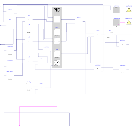
Components
Revisions
-
June 5, 2023, by Jianjun Hu:
Changed the instanceantWinGai2to be conditional.
This is for Buildings, issue 3423. -
May 17, 2022, by Sen Huang:
Changing the gains from parameters to inputs
This is for Buildings, issue 2993. -
April 30, 2021, by Michael Wetter:
Corrected error in non-released development version when reset trigger istrue.
Refactored implementation to have separate blocks that show the P, I and D contribution, each with the control gain applied.
This is for Buildings, issue 2475.