
modelWatersideEconomizer
Waterside economizer controller
Information
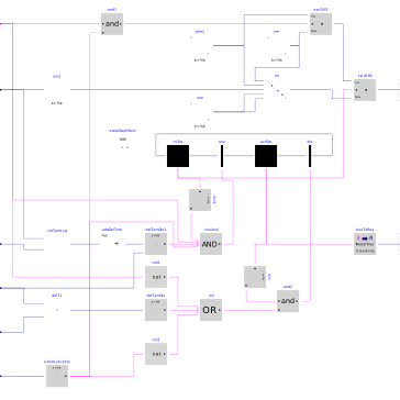
This block implements the control logic for the waterside economizer.
The system is enabled if
- it has been disabled for more than 20 minutes, and
-
the "cooling enabled" input signal is
true, and - the evaporator isolation valve is closed (i.e., the system is not in cold rejection mode), and
-
the predicted leaving water temperature is lower than the entering water
temperature minus
dTEna.
The system is disabled if
- it has been enabled for more than 20 minutes, and
-
the "cooling enabled" input signal is
false, or - the evaporator isolation valve is open, or
-
the leaving water temperature is higher than the entering water
temperature minus
dTDis.
When the system is enabled
- the primary side is controlled so that the primary flow rate varies linearly with the secondary flow rate, and
- the bypass valve on the secondary side is fully closed.
When the system is disabled
-
if the "cooling enabled" input signal is
trueand the evaporator isolation valve is closed, the primary pump (resp. valve) is operated at its minimum speed (resp. opening), otherwise it is switched off (resp. fully closed): this is needed to yield a representative measurement of the service water entering temperature, and - the bypass valve on the secondary side is fully open.
Parameters
| Type | Name | Default | Description |
|---|---|---|---|
| Nominal condition | |||
| Real | m2_flow_nominal | Heat exchanger secondary mass flow rate | |
| Real | T_a1_nominal | Nominal water inlet temperature on district side | |
| Real | T_b2_nominal | Nominal water outlet temperature on building side | |
| Controls | |||
| Real | y1Min | 0.05 | Minimum pump flow rate or valve opening for temperature measurement (fractional) |
| Real | dTEna | 1 | Minimum delta-T above predicted heat exchanger leaving water temperature to enable WSE |
| Real | dTDis | 0.5 | Minimum delta-T across heat exchanger before disabling WSE |
Connectors
| Type | Name | Default | Description |
|---|---|---|---|
| Buildings.Controls.OBC.CDL.Interfaces.BooleanInput | uCoo | Cooling enable signal | |
| Buildings.Controls.OBC.CDL.Interfaces.RealInput | m2_flow | Heat exchanger secondary mass flow rate | |
| Buildings.Controls.OBC.CDL.Interfaces.RealInput | T1WatEnt | Heat exchanger primary water entering temperature | |
| Buildings.Controls.OBC.CDL.Interfaces.RealInput | T2WatEnt | Heat exchanger secondary water entering temperature | |
| Buildings.Controls.OBC.CDL.Interfaces.RealInput | T2WatLvg | Heat exchanger secondary water leaving temperature | |
| Buildings.Controls.OBC.CDL.Interfaces.RealInput | yValIsoEva_actual | Return position of evaporator to ambient loop isolation valve | |
| Buildings.Controls.OBC.CDL.Interfaces.RealOutput | y1 | Primary control signal (pump or valve) | |
| Buildings.Controls.OBC.CDL.Interfaces.RealOutput | yVal2 | Secondary valve control signal |
Components
Revisions
-
March 7, 2025, by Michael Wetter:
Increased, and added where missing, hysteresis, as the input signal is the output of the PID controller. -
July 14, 2021, by Antoine Gautier:
First implementation.