modelHeatRecoveryHeatPump
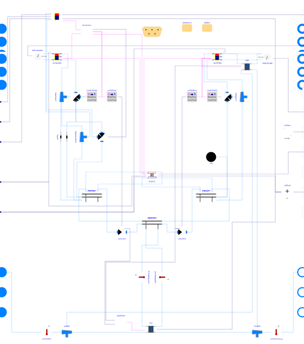
Extends from Buildings.DHC.ETS.BaseClasses.PartialETS (Partial class for modeling an energy transfer station).
Information
Model of an Energy Transfer Station with heat recovery heat pump, buffer tanks and optional domestic hot water preparation and optional water-side economizer.
The figure below shows the schematic diagram. The heat recovery heat pump preferentially operates in heat recovery mode, but if heating (or cooling) demand persists while the cold (or hot) water-side buffer tank is fully charged, the evaporator (or condenser) temperature is reset, the corresponding tank is decoupled to avoid flushing the tank, and heat is exchanged with the district energy system.
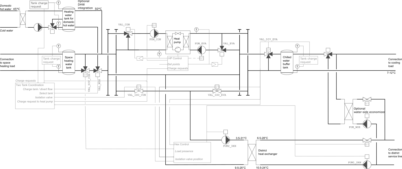
The operation is as follows:
Domestic Hot Water Tank and Buffer Tanks
The chilled water and heating hot water tanks are by default sized for five minutes and used as buffer tanks. The DHW tank is by default sized for 24 hours of storage. Each tank generates a signal to request charging. If the temperature of its supply side (top for the hot tank, bottom for the cold tank) deviates from the set point with hysteresis, charging is enabled until the temperature of its return side (bottom for the hot tank, top for the cold tank) achieves the set point with hysteresis.
When the space heating or cooling tank does not
request charging, the diversion valve VAL_DIV_CON
or VAL_DIV_EVA to the respective tank is closed, and
the isolation valve VAL_ISO_CON or VAL_ISO_EVA
is opened to allow energy exchange with the district
heat exchanger. The diversion valves are necessary
because, for example, when the ETS operates cooling
only mode, rejecting heat to the ambient loop, the
condenser outputs hot water at the minimum leaving
temperature is 15°C. Without the diversion
valve, the cool water from the condenser would flush
out the energy stored in the space heating tank.
This causes energy waste. It also causes short
cycling because the tank will request charging
repeatedly as its temperature falls below the
heating set point, bring the system into a limit
cycle.
Two-tank Coordination on the Condenser Side
The integration of the DHW tank is optional, as not all buildings prepare DHW using the ETS. When integrated, the space heating and DHW tank share the same condenser loop. The table below explains how the two loops are coordinated through valve control.
| Charge signal | Controller output | ||
|---|---|---|---|
| DHW | HHW | ymix | ydiv |
| on | on | 0.5 | 1 |
| on | off | 0 | 1 |
| off | on | 1 | 1 |
| off | off | 1 | 0 |
Heat Recovery Heat Pump
The heat recovery heat pump can produce heating,
cooling, or both simultaneously. The condenser pump
PUM_CON and the evaporator pump PUM_EVA are enabled
when any of the respective tanks requests charging.
The heat pump is turned on 30 seconds after
PUM_CON and PUM_EVA are running.
When on, the primary pumps are operated at constant
speed, and the condenser (resp. evaporator) mixing
valve VAL_CON (resp. VAL_EVA) are modulated with a
P controller to track the set point for the water
that leaves the heat pump, with a small offset to
open first the valve and then ramp up the compressor
speed.
The compressor speed is controlled based on the same temperature measurement as the mixing valves. Based on a moving average of the compressor speed signal for heating and cooling, the heat pump control is switched into heating or cooling dominated operation, and the respective compressor speed setpoint is sent to the heat pump.
If only heating (or only cooling) is requested from the tank, then the evaporator (or condenser) set point temperature is reset to minimize the temperature lift across the heat pump.
District Heat Exchanger
The district heat exchanger hydraulically decouples
the buildings system and the district system. Its
primary and secondary circuits are enabled to operate
if either any of the tanks request charging, and if
an isolation valve VAL_ISO_CON or VAL_ISO_EVA
is open. When enabled, the pumps PUM1_DHX and
PUM2_DHX operate at a constant speed.
Temperature Set Points
The set points for the supply temperatures are input to this
model.
For the heating supply water, use THeaWatSupSet,
for the cooling supply water, use TChiWatSupSet.
If a domestic hot water supply is present, as declared
through the parameter have_hotWat,
then use THotWatSupSet for the set point
temperature to the end user (such as shower),
and use TColWat for the temperature of the cold water supply
and QReqHotWat_flow for the heat flow rate associated
with the hot water supply, i.e.,
QReqHotWat_flow = mHotWat_flow cwat (THotWatSupSet-TColWat), where
mHotWat_flow is the hot water mass flow rate, and
cwat is the specific heat capacity of water.
Domestic Hot Water Preparation
The DHW preparation is optional. If present, a fresh water station is used. The fresh water station allows to store heat in the heating rather than the domestic hot water, therefore avoiding the potential problem of Legionella bacteria getting from the hot water tank to the DHW circuit. This allows to operate the storage at a lower temperature, thereby increasing the heat pump COP.
The integration of the domestic hot water is further described in Buildings.DHC.ETS.Combined.Subsystems.DHWConsumption, which uses the fresh water station that is described and shown with a schematic diagram at Buildings.DHC.ETS.Combined.Subsystems.StorageTankWithExternalHeatExchanger.
Water-side economizer
The water-side economizer is optional. Use of the water-side economizer can improve resilience during heat waves when power consumption of the ETS need to be curtailed by switching of the chiller, for example during a grid outage when the site operates on emergency power.
To use the water-side economizer, if the temperature conditions are favorable, the valves (or pumps) are activated in order to cool the chilled water supply to the building. This model and its operation is described in Buildings.DHC.ETS.Combined.Subsystems.WatersideEconomizer. and in Gautier et al. (2022).
References
Antoine Gautier, Michael Wetter and Matthias Sulzer.
Resilient cooling through geothermal district energy system.
Applied Energy, 325, November, 2022.
Parameters
| Type | Name | Default | Description |
|---|---|---|---|
| Buildings.Fluid.Data.Fuels.Generic[nFue] | fue (from PartialETS) | Fuel type | |
| Buildings.DHC.ETS.Types.ConnectionConfiguration | conCon | Buildings.DHC.ETS.Types.ConnectionConfiguration.Pump | District connection configuration |
| Integer | nSysHea | 1 | Number of heating systems |
| Integer | nSysCoo | nSysHea | Number of cooling systems |
| Integer | nSouAmb | 1 | Number of ambient sources |
| Modelica.Units.SI.MassFlowRate | m1Hex_flow_nominal | abs(QHex_flow_nominal/4200/(T_b1Hex_nominal - T_a1Hex_nominal)) | Design mass flow rate for heat exchanger on district side |
| Modelica.Units.SI.TemperatureDifference | dTOffSetHea | 1 | Temperature to be added to the set point in order to be slightly above what the heating load requires |
| Modelica.Units.SI.TemperatureDifference | dTOffSetCoo | -1 | Temperature to be added to the set point in order to be slightly below what the cooling load requires |
| Buildings.DHC.Loads.HotWater.Data.GenericDomesticHotWaterWithHeatExchanger | datDhw | Performance data of the domestic hot water component | |
| Boolean | have_WSE | false | Set to true in case a waterside economizer is used |
| Modelica.Units.SI.Temperature | THeaWatSupSetMin | datHeaPum.TConLvgMin | Minimum value of heating water supply temperature set point (used for heat pump reset) |
| Configuration | |||
| TypDisSys | typ (from PartialETS) | Buildings.DHC.Types.DistrictSystemType.CombinedGeneration2to4 | Type of district system |
| Integer | nPorts_aHeaWat (from PartialETS) | 0 | Number of heating water return ports |
| Integer | nPorts_bHeaWat (from PartialETS) | 0 | Number of heating water supply ports |
| Integer | nPorts_aChiWat (from PartialETS) | 0 | Number of chilled water return ports |
| Integer | nPorts_bChiWat (from PartialETS) | 0 | Number of chilled water supply ports |
| Boolean | have_heaWat (from PartialETS) | false | Set to true if the ETS supplies heating water |
| Boolean | have_hotWat (from PartialETS) | false | Set to true if the ETS supplies hot water |
| Boolean | have_chiWat (from PartialETS) | false | Set to true if the ETS supplies chilled water |
| Boolean | have_fan (from PartialETS) | false | Set to true if fan power is computed |
| Boolean | have_pum (from PartialETS) | false | Set to true if pump power is computed |
| Boolean | have_eleHea (from PartialETS) | false | Set to true if the ETS has electric heating system |
| Integer | nFue (from PartialETS) | 0 | Number of fuel types (0 means no combustion system) |
| Boolean | have_eleCoo (from PartialETS) | false | Set to true if the ETS has electric cooling system |
| Boolean | have_weaBus (from PartialETS) | false | Set to true to use a weather bus |
| Assumptions | |||
| Boolean | allowFlowReversalSer (from PartialETS) | false | Set to true to allow flow reversal on service side |
| Boolean | allowFlowReversalBui (from PartialETS) | false | Set to true to allow flow reversal on building side |
| Nominal condition | |||
| Modelica.Units.SI.HeatFlowRate | QHeaWat_flow_nominal (from PartialETS) | 0 | Nominal capacity of heating system (>=0) |
| Modelica.Units.SI.HeatFlowRate | QHotWat_flow_nominal (from PartialETS) | 0 | Nominal capacity of hot water production system (>=0) |
| Modelica.Units.SI.HeatFlowRate | QChiWat_flow_nominal (from PartialETS) | 0 | Nominal capacity of cooling system (<=0) |
| Modelica.Units.SI.PressureDifference | dpValIso_nominal | 2E3 | Nominal pressure drop of ambient circuit isolation valves |
| District heat exchanger | |||
| Modelica.Units.SI.PressureDifference | dp1Hex_nominal | Nominal pressure drop across heat exchanger on district side | |
| Modelica.Units.SI.PressureDifference | dp2Hex_nominal | Nominal pressure drop across heat exchanger on building side | |
| Modelica.Units.SI.HeatFlowRate | QHex_flow_nominal | Nominal heat flow rate through heat exchanger (from district to building) | |
| Modelica.Units.SI.Temperature | T_a1Hex_nominal | Nominal water inlet temperature on district side | |
| Modelica.Units.SI.Temperature | T_b1Hex_nominal | Nominal water outlet temperature on district side | |
| Modelica.Units.SI.Temperature | T_a2Hex_nominal | Nominal water inlet temperature on building side | |
| Modelica.Units.SI.Temperature | T_b2Hex_nominal | Nominal water outlet temperature on building side | |
| Real | spePum1HexMin | 0.1 | Heat exchanger primary pump minimum speed (fractional) |
| Real | spePum2HexMin | 0.1 | Heat exchanger secondary pump minimum speed (fractional) |
| Buffer Tank | |||
| Modelica.Units.SI.Volume | VTanHeaWat | datHeaPum.PLRMin*datHeaPum.mCon_flow_nominal*5*60/1000 | Heating water tank volume |
| Modelica.Units.SI.Length | hTanHeaWat | (VTanHeaWat*16/Modelica.Constants.pi)^(1/3) | Heating water tank height (without insulation, assuming twice the diameter) |
| Modelica.Units.SI.Length | dInsTanHeaWat | 0.1 | Heating water tank insulation thickness |
| Modelica.Units.SI.Volume | VTanChiWat | datHeaPum.PLRMin*datHeaPum.mEva_flow_nominal*5*60/1000 | Chilled water tank volume |
| Modelica.Units.SI.Length | hTanChiWat | (VTanChiWat*16/Modelica.Constants.pi)^(1/3) | Chilled water tank height (without insulation, assuming twice the diameter) |
| Modelica.Units.SI.Length | dInsTanChiWat | 0.1 | Chilled water tank insulation thickness |
| Integer | nSegTan | 3 | Number of volume segments for tanks |
| Heat recovery heat pump | |||
| Buildings.DHC.ETS.Combined.Data.GenericHeatPump | datHeaPum | Heat pump performance data | |
| Modelica.Units.SI.PressureDifference | dpCon_nominal | datHeaPum.datHea.dpCon_nominal | Nominal pressure drop across condenser |
| Modelica.Units.SI.PressureDifference | dpEva_nominal | datHeaPum.datHea.dpEva_nominal | Nominal pressure drop across evaporator |
| Supervisory controller | |||
| Buildings.Controls.OBC.CDL.Types.SimpleController | controllerType | Buildings.Controls.OBC.CDL.Types.SimpleController.PI | Type of controller |
| Real | kHot | 0.05 | Gain of controller on hot side |
| Real | kCol | 0.1 | Gain of controller on cold side |
| Modelica.Units.SI.Time | TiHot | 300 | Time constant of integrator block on hot side |
| Modelica.Units.SI.Time | TiCol | 120 | Time constant of integrator block on cold side |
| Modelica.Units.SI.Temperature | TChiWatSupSetMax | datHeaPum.TEvaLvgMax | Maximum value of chilled water supply temperature set point for heat pump (used for heat pump reset) |
| Waterside economizer | |||
| Modelica.Units.SI.PressureDifference | dp1WSE_nominal | 40E3 | Nominal pressure drop across heat exchanger on district side |
| Modelica.Units.SI.PressureDifference | dp2WSE_nominal | 40E3 | Nominal pressure drop across heat exchanger on building side |
| Modelica.Units.SI.HeatFlowRate | QWSE_flow_nominal | 0 | Nominal heat flow rate through water-side economizer exchanger (<=0) |
| Modelica.Units.SI.Temperature | T_a1WSE_nominal | 279.15 | Nominal water inlet temperature on district side |
| Modelica.Units.SI.Temperature | T_b1WSE_nominal | 284.15 | Nominal water outlet temperature on district side |
| Modelica.Units.SI.Temperature | T_a2WSE_nominal | 288.15 | Nominal water inlet temperature on building side |
| Modelica.Units.SI.Temperature | T_b2WSE_nominal | 281.15 | Nominal water outlet temperature on building side |
| Real | y1WSEMin | 0.05 | Minimum pump flow rate or valve opening for temperature measurement (fractional) |
| Modelica.Units.SI.MassFlowRate | m1WSE_flow_nominal | abs(QWSE_flow_nominal/4200/(T_b1WSE_nominal - T_a1WSE_nominal)) | WSE primary mass flow rate |
| Initialization | |||
| MediumBui.Temperature | TCon_start | MediumBui.T_default | Temperature start value on the condenser side |
| MediumBui.Temperature | TEva_start | MediumBui.T_default | Temperature start value on the evaporator side |
Connectors
| Type | Name | Default | Description |
|---|---|---|---|
| Modelica.Fluid.Interfaces.FluidPorts_a[nPorts_aHeaWat] | ports_aHeaWat (from PartialETS) | Fluid connectors for heating water return (from building) | |
| Modelica.Fluid.Interfaces.FluidPorts_b[nPorts_bHeaWat] | ports_bHeaWat (from PartialETS) | Fluid connectors for heating water supply (to building) | |
| Modelica.Fluid.Interfaces.FluidPorts_a[nPorts_aChiWat] | ports_aChiWat (from PartialETS) | Fluid connectors for chilled water return (from building) | |
| Modelica.Fluid.Interfaces.FluidPorts_b[nPorts_bChiWat] | ports_bChiWat (from PartialETS) | Fluid connectors for chilled water supply (to building) | |
| Modelica.Fluid.Interfaces.FluidPort_a | port_aSerAmb (from PartialETS) | Fluid connector for ambient water service supply line | |
| Modelica.Fluid.Interfaces.FluidPort_b | port_bSerAmb (from PartialETS) | Fluid connector for ambient water service return line | |
| Modelica.Fluid.Interfaces.FluidPort_a | port_aSerHea (from PartialETS) | Fluid connector for heating service supply line | |
| Modelica.Fluid.Interfaces.FluidPort_b | port_bSerHea (from PartialETS) | Fluid connector for heating service return line | |
| Modelica.Fluid.Interfaces.FluidPort_a | port_aSerCoo (from PartialETS) | Fluid connector for cooling service supply line | |
| Modelica.Fluid.Interfaces.FluidPort_b | port_bSerCoo (from PartialETS) | Fluid connector for cooling service return line | |
| Buildings.Controls.OBC.CDL.Interfaces.RealOutput | PHea (from PartialETS) | Power drawn by heating system | |
| Buildings.Controls.OBC.CDL.Interfaces.RealOutput | PCoo (from PartialETS) | Power drawn by cooling system | |
| Buildings.Controls.OBC.CDL.Interfaces.RealOutput | PFan (from PartialETS) | Power drawn by fan motors | |
| Buildings.Controls.OBC.CDL.Interfaces.RealOutput | PPum (from PartialETS) | Power drawn by pump motors | |
| Buildings.Controls.OBC.CDL.Interfaces.RealOutput[nFue] | QFue_flow (from PartialETS) | Fuel energy input rate | |
| BoundaryConditions.WeatherData.Bus | weaBus (from PartialETS) | Weather data bus | |
| Buildings.Controls.OBC.CDL.Interfaces.RealInput | THeaWatSupSet | Heating water supply temperature set point | |
| Buildings.Controls.OBC.CDL.Interfaces.RealInput | TChiWatSupSet | Chilled water supply temperature set point | |
| Buildings.Controls.OBC.CDL.Interfaces.RealOutput | dHHeaWat_flow | Heating water distributed energy flow rate | |
| Buildings.Controls.OBC.CDL.Interfaces.RealOutput | dHChiWat_flow | Chilled water distributed energy flow rate | |
| Buildings.Controls.OBC.CDL.Interfaces.RealInput | THotWatSupSet | Domestic hot water temperature set point for supply to fixtures | |
| Buildings.Controls.OBC.CDL.Interfaces.RealInput | TColWat | Cold water temperature that is fed to domestic hot water preparation | |
| Buildings.Controls.OBC.CDL.Interfaces.RealInput | QReqHotWat_flow | Domestic hot water load | |
| Buildings.Controls.OBC.CDL.Interfaces.RealOutput | dHHotWat_flow | Domestic hot water distributed energy flow rate |
Components
| Type | Name | Default | Description |
|---|---|---|---|
| Buildings.DHC.ETS.Combined.Subsystems.HeatPumpModular | heaPum | Heat pump | |
| Buildings.DHC.ETS.Combined.Subsystems.HeatExchanger | hex | District heat exchanger | |
| Buildings.DHC.ETS.Combined.Subsystems.StratifiedTankWithCommand | tanChiWat | Chilled water tank | |
| Buildings.DHC.ETS.Combined.Subsystems.StratifiedTankWithCommand | tanHeaWat | Heating hot water tank | |
| Buildings.DHC.ETS.Combined.Subsystems.DHWConsumption | tanDhw | Tank for domestic hot water | |
| Buildings.Fluid.Actuators.Valves.TwoWayLinear | valIsoEva | Evaporator to ambient loop isolation valve | |
| Buildings.Fluid.Actuators.Valves.TwoWayLinear | valIsoCon | Condenser to ambient loop isolation valve | |
| Buildings.DHC.ETS.BaseClasses.CollectorDistributor | colChiWat | Collector/distributor for chilled water | |
| Buildings.DHC.ETS.BaseClasses.CollectorDistributor | colHeaWat | Collector/distributor for heating water | |
| Buildings.DHC.ETS.BaseClasses.CollectorDistributor | colAmbWat | Collector/distributor for ambient water | |
| Buildings.DHC.Networks.BaseClasses.DifferenceEnthalpyFlowRate | dHFloHeaWat | Variation of enthalpy flow rate | |
| Buildings.Fluid.Sensors.TemperatureTwoPort | senTHexBuiEnt | Heat exchanger water entering temperature on building side | |
| Buildings.Fluid.Sensors.TemperatureTwoPort | senTHexBuiLvg | Heat exchanger water leaving temperature on building side | |
| Buildings.Fluid.Sources.Boundary_pT | bou | Pressure boundary condition representing expansion vessel (common to HHW and CHW) | |
| Buildings.Controls.OBC.CDL.Reals.MultiSum | totPPum | Total pump power | |
| Buildings.DHC.Networks.BaseClasses.DifferenceEnthalpyFlowRate | dHFloChiWat | Variation of enthalpy flow rate | |
| Buildings.Controls.OBC.CDL.Reals.Sources.Constant | zerPHea | Zero power | |
| Buildings.Fluid.Actuators.Valves.ThreeWayLinear | valMixHea | Three way valve selecting condenser flow from HHW or DHW return | |
| Buildings.Fluid.FixedResistances.Junction | junDomHotWat | Junction to domestic hot water tank | |
| Buildings.DHC.ETS.Combined.Controls.TwoTankCoordination | twoTanCoo | Controller to coordinate heat rejection vs use in space or DHW tank | |
| Buildings.Controls.OBC.CDL.Conversions.BooleanToReal | conDivValChi | Control for diversion valve to avoid that tank is flushed when changing to district heat exchanger | |
| Buildings.Fluid.Actuators.Valves.ThreeWayLinear | valDivCon | Diversion valve used to reject heat and not flow through the whole tank | |
| Buildings.Fluid.Actuators.Valves.ThreeWayLinear | valDivEva | Diversion valve used to reject cold and not flow through the whole tank | |
| Buildings.Fluid.FixedResistances.Junction | junChiWat | Junction at chilled water tank | |
| Buildings.Fluid.FixedResistances.Junction | junHeaWat | Junction at heating water tank | |
| Buildings.Controls.OBC.CDL.Conversions.BooleanToReal | conAmbEva | Control for valve for ambient loop on evaporator side | |
| Buildings.Controls.OBC.CDL.Conversions.BooleanToReal | conDivValHea | Control for diversion valve to avoid that tank is flushed when changing to district heat exchanger | |
| Buildings.Controls.OBC.CDL.Conversions.BooleanToReal | conAmbCon | Control for valve for ambient loop on condenser side | |
| Buildings.Fluid.Sensors.TemperatureTwoPort | senTSerEnt | Heat exchanger service line water entering temperature | |
| Buildings.Fluid.Sensors.TemperatureTwoPort | senTSerLinLvg | Heat exchanger service line water leaving temperature | |
| Controls.EtsHex | opeEtsHex | Output true to operate ETS heat exchanger | |
| Subsystems.WatersideEconomizer | WSE | Waterside economizer | |
| Buildings.DHC.ETS.BaseClasses.Junction | splWSE | Flow splitter for WSE | |
| Buildings.DHC.ETS.BaseClasses.Junction | mixWSE | Flow mixer for WSE |
Revisions
-
November 14, 2025, by Michael Wetter:
First implementation.