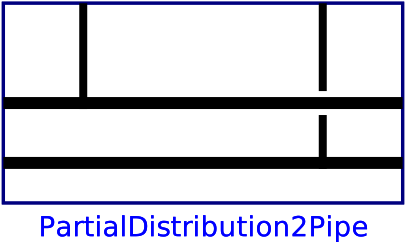
modelPartialDistribution2Pipe
Partial model for two-pipe distribution network
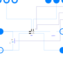
Extends from PartialDistribution (Partial model for distribution network).
Information
Partial model of a two-pipe distribution network.
An array of replaceable partial models is used to represent the connections along the network, including the pipe segment immediately upstream each connection.
A replaceable partial model is used to represent the pipe segment of the supply and return line after the last connection.
The parameter iConDpSen is provided to specify the index of the
connection where the pressure drop is measured.
Use zero for a sensor connected to the supply pipe inlet and return pipe outlet.
Use a negative value if no sensor is needed.
Optionally the heat flow rate transferred to each connected load can be output.
Parameters
| Type | Name | Default | Description |
|---|---|---|---|
| Boolean | show_entFlo | false | Set to true to output enthalpy flow rate difference at each connection |
| General | |||
| Integer | nCon (from PartialDistribution2Medium) | Number of connections | |
| Integer | iConDpSen | nCon | Index of the connection where the pressure drop is measured |
| Assumptions | |||
| Boolean | allowFlowReversal (from PartialDistribution2Medium) | false | = true to allow flow reversal, false restricts to design direction (port_a -> port_b) |
| General › Nominal condition | |||
| Modelica.Units.SI.MassFlowRate | mDis_flow_nominal | Nominal mass flow rate in the distribution line before the first connection | |
| Modelica.Units.SI.MassFlowRate[nCon] | mCon_flow_nominal | Nominal mass flow rate in each connection line | |
| Modelica.Units.SI.MassFlowRate | mEnd_flow_nominal | mDis_flow_nominal - sum(mCon_flow_nominal) | Nominal mass flow rate in the end of the distribution line |
| Modelica.Units.SI.MassFlowRate[nCon] | mDisCon_flow_nominal | cat(1, {mDis_flow_nominal}, {mDis_flow_nominal - sum(mCon_flow_nominal[1:i]) for i in 1:(nCon - 1)}) | Nominal mass flow rate in the distribution line before each connection |
| Dynamics › Conservation equations | |||
| Modelica.Fluid.Types.Dynamics | energyDynamics | Modelica.Fluid.Types.Dynamics.FixedInitial | Type of energy balance: dynamic (3 initialization options) or steady state |
| Dynamics › Nominal condition | |||
| Modelica.Units.SI.Time | tau | 10 | Time constant at nominal flow for dynamic energy and momentum balance |
Connectors
| Type | Name | Default | Description |
|---|---|---|---|
| Modelica.Fluid.Interfaces.FluidPorts_a[nCon] | ports_aCon (from PartialDistribution2Medium) | Connection return ports | |
| Modelica.Fluid.Interfaces.FluidPorts_b[nCon] | ports_bCon (from PartialDistribution2Medium) | Connection supply ports | |
| Modelica.Fluid.Interfaces.FluidPort_a | port_aDisSup (from PartialDistribution2Medium) | Distribution supply inlet port | |
| Modelica.Fluid.Interfaces.FluidPort_b | port_bDisSup (from PartialDistribution2Medium) | Distribution supply outlet port | |
| Modelica.Fluid.Interfaces.FluidPort_b | port_bDisRet | Distribution return outlet port | |
| Modelica.Fluid.Interfaces.FluidPort_a | port_aDisRet | Distribution return inlet port | |
| Buildings.Controls.OBC.CDL.Interfaces.RealOutput | dp | Pressure difference at given location (measured) | |
| Buildings.Controls.OBC.CDL.Interfaces.RealOutput[nCon] | dH_flow | Difference in enthalpy flow rate between connection supply and return | |
| Buildings.Controls.OBC.CDL.Interfaces.RealOutput[nCon] | mCon_flow | Connection supply mass flow rate (measured) |
Components
| Type | Name | Default | Description |
|---|---|---|---|
| Buildings.DHC.Networks.BaseClasses.PartialConnection2Pipe[nCon] | con | Connection to agent | |
| Model_pipDis | pipEnd | Pipe representing the end of the distribution line (after last connection) | |
| Fluid.Sensors.RelativePressure | senRelPre | Relative pressure sensor |
Contents
| Name | Description |
|---|---|
 Model_pipDis Model_pipDis | Model for distribution pipe |
Revisions
-
February 21, 2020, by Antoine Gautier:
First implementation.