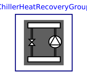
modelChillerHeatRecoveryGroup
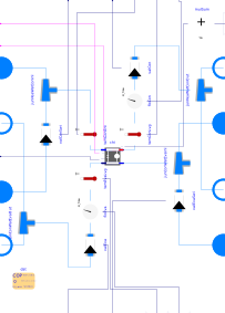
Extends from Buildings.Fluid.Interfaces.PartialEightPortInterface (Partial model with eight ports and declaration of quantities that are used by many models).
Information
This model represents a set of identical heat recovery chillers that are piped in parallel. Modulating isolation valves and modulating switchover valves are included on condenser and evaporator side. The switchover valves allow indexing the condenser (resp. the evaporator) either to the CWC loop or to the HW loop (resp. to the CWE loop or to the CHW loop). Modulating valves are used to allow for sequences of operation that bleed CWE into the HW return flow to modulate the condenser entering temperature.
Control points
The following input and output points are available.
-
On/Off command
y1: DO signal dedicated to each unit, with a dimensionality of one -
Cooling switchover command
y1Coo: DO signal dedicated to each unit, with a dimensionality of one -
Supply temperature setpoint
TSet: AO signal dedicated to each unit, with a dimensionality of one The signal corresponds either to the HW supply temperature setpoint when the unit operates in heating mode, or to the CHW supply temperature setpoint when the unit operates in cooling mode. -
Condenser and evaporator isolation valve commanded position
yVal(Con|Eva): AO signal dedicated to each unit, with a dimensionality of one -
Condenser and evaporator switchover valve commanded position
yVal(Con|Eva)Swi: AO signal dedicated to each unit, with a dimensionality of one -
Condenser and evaporator leaving temperature
T(Con|Eva)Lvg: AI signal dedicated to each unit, with a dimensionality of one -
Condenser entering temperature
TConEnt: AI signal dedicated to each unit, with a dimensionality of one -
Condenser and evaporator mass flow rate
m(Con|Eva)_flow: AI signal dedicated to each unit, with a dimensionality of one
Details
HRC performance data
The performance data should cover the HRC lift envelope,
that is when the HRC is operating in direct heat recovery mode,
producing CHW and HW at their setpoint value at full load.
In this case, and to allow for cascading heat recovery where
a third fluid circuit is used to generate a cascade of thermodynamic cycles,
two additional parameters TCasEntCoo_nominal and
TCasEntHea_nominal are exposed to specify the
entering temperature of the third fluid circuit when
the HRC is operating in cooling mode and in heating mode,
respectively.
In cooling mode the third fluid circuit is connected to the
condenser barrel.
In heating mode, the third fluid circuit is connected to the
evaporator barrel.
The parameters TCasEnt*_nominal are then used to assess the
design capacity in heating and cooling mode, respectively.
Actuators
By default, linear valve models are used. Those are configured with a pressure drop varying linearly with the flow rate, as opposed to the quadratic dependency usually considered for a turbulent flow regime. This is because the whole plant model contains large nonlinear systems of equations and this configuration limits the risk of solver failure while reducing the time to solution. This has no significant impact on the operating point of the circulation pumps when a control loop is used to modulate the valve opening and maintain the flow rate or the leaving temperature at setpoint. Then, whatever the modeling assumptions for the valve, the control loop ensures that the valve creates the adequate pressure drop and flow, which will simply be reached at a different valve opening with the above simplification.
Parameters
| Type | Name | Default | Description |
|---|---|---|---|
| Integer | nUni | Number of units operating at design conditions | |
| Modelica.Units.SI.Temperature | TCasHeaEnt_nominal | 298.15 | Design evaporator entering temperature in cascading heating mode |
| Modelica.Units.SI.Temperature | TCasCooEnt_nominal | 288.15 | Design condenser entering temperature in cascading cooling mode |
| Modelica.Units.SI.Temperature | TChiWatSup_nominal | dat.TEvaLvg_nominal | Design (minimum) CHW supply temperature |
| Modelica.Units.SI.Temperature | THeaWatSup_nominal | dat.TConLvg_nominal | Design (maximum) HW supply temperature |
| Modelica.Units.SI.Efficiency | COPCasHea_nominal | Coefficient of performance in cascading heating mode | |
| Modelica.Units.SI.Efficiency | COPCasCoo_nominal | Coefficient of performance in cascading cooling mode | |
| Modelica.Units.SI.Temperature | TCasHeaLvg_nominal | Design value of evaporator leaving temperature in cascading heating mode | |
| Modelica.Units.SI.Temperature | TCasCooLvg_nominal | Design value of condenser leaving temperature in cascading cooling mode | |
| Fluid.Chillers.Data.ElectricReformulatedEIR.Generic | dat | Chiller parameters (each unit) | |
| Assumptions | |||
| Boolean | allowFlowReversal1 (from EightPort) | true | = true to allow flow reversal in medium 1, false restricts to design direction (port_a -> port_b) |
| Boolean | allowFlowReversal2 (from EightPort) | true | = true to allow flow reversal in medium 2, false restricts to design direction (port_a -> port_b) |
| Boolean | allowFlowReversal3 (from EightPort) | true | = true to allow flow reversal in medium 3, false restricts to design direction (port_a -> port_b) |
| Boolean | allowFlowReversal4 (from EightPort) | true | = true to allow flow reversal in medium 4, false restricts to design direction (port_a -> port_b) |
| Boolean | allowFlowReversal | true | = false to simplify equations, assuming, but not enforcing, no flow reversal |
| Advanced › Initialization | |||
| Modelica.Units.SI.SpecificEnthalpy | h_outflow_a1_start (from EightPort) | Medium1.h_default | Start value for enthalpy flowing out of port a1 |
| Modelica.Units.SI.SpecificEnthalpy | h_outflow_b1_start (from EightPort) | Medium1.h_default | Start value for enthalpy flowing out of port b1 |
| Modelica.Units.SI.SpecificEnthalpy | h_outflow_a2_start (from EightPort) | Medium2.h_default | Start value for enthalpy flowing out of port a2 |
| Modelica.Units.SI.SpecificEnthalpy | h_outflow_b2_start (from EightPort) | Medium2.h_default | Start value for enthalpy flowing out of port b2 |
| Modelica.Units.SI.SpecificEnthalpy | h_outflow_a3_start (from EightPort) | Medium3.h_default | Start value for enthalpy flowing out of port a1 |
| Modelica.Units.SI.SpecificEnthalpy | h_outflow_b3_start (from EightPort) | Medium3.h_default | Start value for enthalpy flowing out of port b1 |
| Modelica.Units.SI.SpecificEnthalpy | h_outflow_a4_start (from EightPort) | Medium4.h_default | Start value for enthalpy flowing out of port a1 |
| Modelica.Units.SI.SpecificEnthalpy | h_outflow_b4_start (from EightPort) | Medium4.h_default | Start value for enthalpy flowing out of port b1 |
| Nominal condition | |||
| Modelica.Units.SI.MassFlowRate | m1_flow_nominal (from PartialEightPortInterface) | Nominal mass flow rate | |
| Modelica.Units.SI.MassFlowRate | m2_flow_nominal (from PartialEightPortInterface) | Nominal mass flow rate | |
| Modelica.Units.SI.MassFlowRate | m3_flow_nominal (from PartialEightPortInterface) | Nominal mass flow rate | |
| Modelica.Units.SI.MassFlowRate | m4_flow_nominal (from PartialEightPortInterface) | Nominal mass flow rate | |
| Modelica.Units.SI.HeatFlowRate | QChiWatUni_flow_nominal | dat.QEva_flow_nominal | Design cooling heat flow rate (each unit, <0) |
| Modelica.Units.SI.HeatFlowRate | QHeaWatUni_flow_nominal | -dat.QEva_flow_nominal*(1 + 1/dat.COP_nominal*dat.etaMotor) | Design heating heat flow rate in direct heat recovery mode (each unit, >0) |
| Modelica.Units.SI.HeatFlowRate | QEvaCasHeaUni_flow_nominal | Design evaporator heat flow rate in cascading heating mode (each unit, <0) | |
| Modelica.Units.SI.HeatFlowRate | QChiWatCasCooUni_flow_nominal | Design cooling heat flow rate in cascading cooling mode (each unit, <0) | |
| Modelica.Units.SI.HeatFlowRate | QHeaWatCasHeaUni_flow_nominal | -QEvaCasHeaUni_flow_nominal*(1 + 1/COPCasHea_nominal*dat.etaMotor) | Design heating heat flow rate in cascading heating mode (each unit, >0) |
| Modelica.Units.SI.HeatFlowRate | QConCasCooUni_flow_nominal | -QChiWatCasCooUni_flow_nominal*(1 + 1/COPCasCoo_nominal*dat.etaMotor) | Design condenser heat flow rate in cascading cooling mode (each unit, >0) |
| Modelica.Units.SI.HeatFlowRate | QChiWat_flow_nominal | nUni*QChiWatUni_flow_nominal | Design cooling heat flow rate (all units, <0) |
| Modelica.Units.SI.HeatFlowRate | QHeaWat_flow_nominal | nUni*QHeaWatUni_flow_nominal | Design heating heat flow rate (all units, >0) |
| Modelica.Units.SI.HeatFlowRate | QEvaCasHea_flow_nominal | nUni*QEvaCasHeaUni_flow_nominal | Design evaporator heat flow rate in cascading heating mode (all units, <0) |
| Modelica.Units.SI.HeatFlowRate | QChiWatCasCoo_flow_nominal | nUni*QChiWatCasCooUni_flow_nominal | Design cooling heat flow rate in cascading cooling mode (all units, <0) |
| Modelica.Units.SI.HeatFlowRate | QHeaWatCasHea_flow_nominal | nUni*QHeaWatCasHeaUni_flow_nominal | Design heating heat flow rate in cascading heating mode (all units, >0) |
| Modelica.Units.SI.HeatFlowRate | QConCasCoo_flow_nominal | nUni*QConCasCooUni_flow_nominal | Design condenser heat flow rate in cascading cooling mode (all units, >0) |
| Modelica.Units.SI.MassFlowRate | mChiWatUni_flow_nominal | dat.mEva_flow_nominal | Design CHW mass flow rate (each unit) |
| Modelica.Units.SI.MassFlowRate | mConWatUni_flow_nominal | dat.mCon_flow_nominal | Design CW mass flow rate (each unit) |
| Modelica.Units.SI.MassFlowRate | mChiWat_flow_nominal | nUni*mChiWatUni_flow_nominal | Design CHW mass flow rate (all units) |
| Modelica.Units.SI.MassFlowRate | mConWat_flow_nominal | nUni*mConWatUni_flow_nominal | Design CW mass flow rate (all units) |
| Modelica.Units.SI.PressureDifference | dpEva_nominal | Design evaporator pressure drop (each unit) | |
| Modelica.Units.SI.PressureDifference | dpCon_nominal | Design condenser pressure drop (each unit) | |
| Advanced | |||
| Medium1.MassFlowRate | m1_flow_small (from PartialEightPortInterface) | 1E-4*abs(m1_flow_nominal) | Small mass flow rate for regularization of zero flow |
| Medium2.MassFlowRate | m2_flow_small (from PartialEightPortInterface) | 1E-4*abs(m2_flow_nominal) | Small mass flow rate for regularization of zero flow |
| Medium3.MassFlowRate | m3_flow_small (from PartialEightPortInterface) | 1E-4*abs(m3_flow_nominal) | Small mass flow rate for regularization of zero flow |
| Medium4.MassFlowRate | m4_flow_small (from PartialEightPortInterface) | 1E-4*abs(m4_flow_nominal) | Small mass flow rate for regularization of zero flow |
| Advanced › Diagnostics | |||
| Boolean | show_T (from PartialEightPortInterface) | false | = true, if actual temperature at port is computed |
| Dynamics › Conservation equations | |||
| Modelica.Fluid.Types.Dynamics | energyDynamics | Modelica.Fluid.Types.Dynamics.DynamicFreeInitial | Type of energy balance: dynamic (3 initialization options) or steady state |
| Dynamics › Time needed to open or close valve | |||
| Boolean | use_strokeTime | energyDynamics <> Modelica.Fluid.Types.Dynamics.SteadyState | Set to true to continuously open and close valve |
| Modelica.Units.SI.Time | strokeTime | 120 | Time needed to open or close valve |
| Modelica.Blocks.Types.Init | init | Modelica.Blocks.Types.Init.InitialOutput | Type of initialization (no init/steady state/initial state/initial output) |
| Real | y_start | 1 | Initial position of actuator |
Connectors
| Type | Name | Default | Description |
|---|---|---|---|
| Modelica.Fluid.Interfaces.FluidPort_a | port_a1 (from EightPort) | Fluid connector a1 (positive design flow direction is from port_a1 to port_b1) | |
| Modelica.Fluid.Interfaces.FluidPort_b | port_b1 (from EightPort) | Fluid connector b1 (positive design flow direction is from port_a1 to port_b1) | |
| Modelica.Fluid.Interfaces.FluidPort_a | port_a2 (from EightPort) | Fluid connector a2 (positive design flow direction is from port_a2 to port_b2) | |
| Modelica.Fluid.Interfaces.FluidPort_b | port_b2 (from EightPort) | Fluid connector b2 (positive design flow direction is from port_a2 to port_b2) | |
| Modelica.Fluid.Interfaces.FluidPort_a | port_a3 (from EightPort) | Fluid connector a1 (positive design flow direction is from port_a3 to port_b3) | |
| Modelica.Fluid.Interfaces.FluidPort_b | port_b3 (from EightPort) | Fluid connector b2 (positive design flow direction is from port_a3 to port_b3) | |
| Modelica.Fluid.Interfaces.FluidPort_a | port_a4 (from EightPort) | Fluid connector a1 (positive design flow direction is from port_a4 to port_b4) | |
| Modelica.Fluid.Interfaces.FluidPort_b | port_b4 (from EightPort) | Fluid connector b2 (positive design flow direction is from port_a4 to port_b4) | |
| Buildings.Controls.OBC.CDL.Interfaces.BooleanInput[nUni] | y1 | Chiller On/Off command | |
| Buildings.Controls.OBC.CDL.Interfaces.BooleanInput[nUni] | y1Coo | Cooling switchover command: true for cooling, false for heating | |
| Buildings.Controls.OBC.CDL.Interfaces.RealInput[nUni] | TSet | Supply temperature setpoint | |
| Buildings.Controls.OBC.CDL.Interfaces.RealInput[nUni] | yValConSwi | Chiller condenser switchover valve commanded position | |
| Buildings.Controls.OBC.CDL.Interfaces.RealInput[nUni] | yValEvaSwi | Chiller evaporator switchover valve commanded position | |
| Buildings.Controls.OBC.CDL.Interfaces.RealOutput | P | Power drawn | |
| Buildings.Controls.OBC.CDL.Interfaces.RealInput[nUni] | yValCon | Chiller condenser isolation valve commanded position | |
| Buildings.Controls.OBC.CDL.Interfaces.RealInput[nUni] | yValEva | Chiller evaporator isolation valve commanded position | |
| Buildings.Controls.OBC.CDL.Interfaces.RealOutput[nUni] | mEva_flow | Chiller evaporator barrel mass flow rate | |
| Buildings.Controls.OBC.CDL.Interfaces.RealOutput[nUni] | TEvaLvg | Chiller evaporator leaving temperature | |
| Buildings.Controls.OBC.CDL.Interfaces.RealOutput[nUni] | mCon_flow | Chiller condenser barrel mass flow rate | |
| Buildings.Controls.OBC.CDL.Interfaces.RealOutput[nUni] | TConLvg | Chiller condenser leaving temperature | |
| Buildings.Controls.OBC.CDL.Interfaces.RealOutput[nUni] | TConEnt | Chiller condenser entering temperature |
Components
| Type | Name | Default | Description |
|---|---|---|---|
| Medium1.MassFlowRate | m1_flow (from PartialEightPortInterface) | port_a1.m_flow | Mass flow rate from port_a1 to port_b1 (m1_flow > 0 is design flow direction) |
| Modelica.Units.SI.Pressure | dp1 (from PartialEightPortInterface) | port_a1.p - port_b1.p | Pressure difference between port_a1 and port_b1 |
| Medium2.MassFlowRate | m2_flow (from PartialEightPortInterface) | port_a2.m_flow | Mass flow rate from port_a2 to port_b2 (m2_flow > 0 is design flow direction) |
| Modelica.Units.SI.Pressure | dp2 (from PartialEightPortInterface) | port_a2.p - port_b2.p | Pressure difference between port_a2 and port_b2 |
| Medium3.MassFlowRate | m3_flow (from PartialEightPortInterface) | port_a3.m_flow | Mass flow rate from port_a3 to port_b3 (m3_flow > 0 is design flow direction) |
| Modelica.Units.SI.Pressure | dp3 (from PartialEightPortInterface) | port_a3.p - port_b3.p | Pressure difference between port_a3 and port_b3 |
| Medium4.MassFlowRate | m4_flow (from PartialEightPortInterface) | port_a4.m_flow | Mass flow rate from port_a4 to port_b4 (m4_flow > 0 is design flow direction) |
| Modelica.Units.SI.Pressure | dp4 (from PartialEightPortInterface) | port_a4.p - port_b4.p | Pressure difference between port_a4 and port_b4 |
| Medium1.ThermodynamicState | sta_a1 (from PartialEightPortInterface) | if allowFlowReversal1 then Medium1.setState_phX(port_a1.p, noEvent(actualStream(port_a1.h_outflow)), noEvent(actualStream(port_a1.Xi_outflow))) else Medium1.setState_phX(port_a1.p, inStream(port_a1.h_outflow), inStream(port_a1.Xi_outflow)) | Medium properties in port_a1 |
| Medium1.ThermodynamicState | sta_b1 (from PartialEightPortInterface) | if allowFlowReversal1 then Medium1.setState_phX(port_b1.p, noEvent(actualStream(port_b1.h_outflow)), noEvent(actualStream(port_b1.Xi_outflow))) else Medium1.setState_phX(port_b1.p, port_b1.h_outflow, port_b1.Xi_outflow) | Medium properties in port_b1 |
| Medium2.ThermodynamicState | sta_a2 (from PartialEightPortInterface) | if allowFlowReversal2 then Medium2.setState_phX(port_a2.p, noEvent(actualStream(port_a2.h_outflow)), noEvent(actualStream(port_a2.Xi_outflow))) else Medium2.setState_phX(port_a2.p, inStream(port_a2.h_outflow), inStream(port_a2.Xi_outflow)) | Medium properties in port_a2 |
| Medium2.ThermodynamicState | sta_b2 (from PartialEightPortInterface) | if allowFlowReversal2 then Medium2.setState_phX(port_b2.p, noEvent(actualStream(port_b2.h_outflow)), noEvent(actualStream(port_b2.Xi_outflow))) else Medium2.setState_phX(port_b2.p, port_b2.h_outflow, port_b2.Xi_outflow) | Medium properties in port_b2 |
| Medium3.ThermodynamicState | sta_a3 (from PartialEightPortInterface) | if allowFlowReversal3 then Medium3.setState_phX(port_a3.p, noEvent(actualStream(port_a3.h_outflow)), noEvent(actualStream(port_a3.Xi_outflow))) else Medium3.setState_phX(port_a3.p, inStream(port_a3.h_outflow), inStream(port_a3.Xi_outflow)) | Medium properties in port_a3 |
| Medium3.ThermodynamicState | sta_b3 (from PartialEightPortInterface) | if allowFlowReversal3 then Medium3.setState_phX(port_b3.p, noEvent(actualStream(port_b3.h_outflow)), noEvent(actualStream(port_b3.Xi_outflow))) else Medium3.setState_phX(port_b3.p, port_b3.h_outflow, port_b3.Xi_outflow) | Medium properties in port_b3 |
| Medium4.ThermodynamicState | sta_a4 (from PartialEightPortInterface) | if allowFlowReversal4 then Medium4.setState_phX(port_a4.p, noEvent(actualStream(port_a4.h_outflow)), noEvent(actualStream(port_a4.Xi_outflow))) else Medium4.setState_phX(port_a4.p, inStream(port_a4.h_outflow), inStream(port_a4.Xi_outflow)) | Medium properties in port_a4 |
| Medium4.ThermodynamicState | sta_b4 (from PartialEightPortInterface) | if allowFlowReversal4 then Medium4.setState_phX(port_b4.p, noEvent(actualStream(port_b4.h_outflow)), noEvent(actualStream(port_b4.Xi_outflow))) else Medium4.setState_phX(port_b4.p, port_b4.h_outflow, port_b4.Xi_outflow) | Medium properties in port_b4 |
| Fluid.Chillers.ElectricReformulatedEIR[nUni] | chi | Chiller | |
| Fluid.Actuators.Valves.TwoWayLinear[nUni] | valCon | Condenser isolation valve | |
| Fluid.Actuators.Valves.TwoWayLinear[nUni] | valEva | Evaporator isolation valve | |
| Fluid.FixedResistances.Junction[nUni] | junConWatEvaOut | Fluid junction | |
| Fluid.FixedResistances.Junction[nUni] | junConWatEvaInl | Fluid junction | |
| Fluid.Sensors.TemperatureTwoPort[nUni] | temEvaLvg | Chiller evaporator leaving temperature | |
| Fluid.FixedResistances.Junction[nUni] | junHeaWatConInl | Fluid junction | |
| Fluid.FixedResistances.Junction[nUni] | junHeaWatConOut | Fluid junction | |
| Fluid.Sensors.TemperatureTwoPort[nUni] | temConEnt | Chiller condenser entering temperature | |
| Fluid.Sensors.TemperatureTwoPort[nUni] | temConLvg | Chiller condenser leaving temperature | |
| Buildings.Controls.OBC.CDL.Reals.MultiSum | mulSum | Sum up power of all units | |
| Fluid.Sensors.MassFlowRate[nUni] | floEva | Chiller evaporator barrel mass flow rate | |
| Fluid.Sensors.MassFlowRate[nUni] | floCon | Chiller condenser barrel mass flow rate | |
| Fluid.Actuators.Valves.TwoWayLinear[nUni] | valConSwi | Condenser switchover valve | |
| Fluid.Actuators.Valves.TwoWayLinear[nUni] | valEvaSwi | Evaporator switchover valve |
Contents
| Name | Description |
|---|---|
 Medium Medium |
Revisions
-
February 24, 2023, by Antoine Gautier:
First implementation.