
modelACSimpleGrid
Test model for a network model
Extends from Modelica.Icons.Example (Icon for runnable examples).
Information
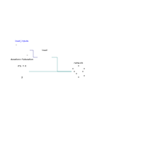
This example demonstrates how to use a network model to connect a source to a load. In this simple case the network has two nodes that are connected by a commercial line cable.
At the beginning of the simulation the load consumes power while at the and it produces power. The voltage at the load at the beginning is lower than the nominal RMS voltage (480 V) while at the end of the simulation it is higher. The voltage drop and increase are due to the presence of the cable between the source and the load.
The network uses cables of the type LowVoltageCable.Cu35 with
a length of 200 m.
The picture below describes the grid topology.

Components
| Type | Name | Default | Description |
|---|---|---|---|
| ThreePhasesBalanced.Lines.Network | network | Network model that represents the connection between the source and the load | |
| ThreePhasesBalanced.Loads.Inductive | load | Load connected to the network | |
| ThreePhasesBalanced.Sources.FixedVoltage | E | Voltage source | |
| Modelica.Blocks.Sources.Ramp | load_inputs | Input signal for the power consumption of the loads |
Revisions
-
September 22, 2014, by Marco Bonvini:
Documentation and example revised.