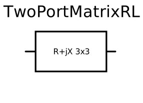
modelTwoPortMatrixRL
Model of an RL line parameterized with impedance matrices

Extends from Buildings.Electrical.AC.ThreePhasesUnbalanced.Interfaces.TwoPort (Partial model interface for a two port component without neutral cable).
Information
Resistive-inductive model that connects two AC three-phase unbalanced interfaces. This model can be used to represent a cable in a three-phase unbalanced AC system. The voltage between the ports is

where Vi{p,n} is the voltage phasor at the connector p or
n of the i-th phase, while Iip
the current phasor entering from the connector p of the i-th phase.
The model is parameterized with an impedance matrix Z. The matrix is symmetric thus just the upper triangular part of it has to be defined.
Parameters
| Type | Name | Default | Description |
|---|---|---|---|
| Modelica.Units.SI.Impedance[2] | Z11 | Element [1,1] of impedance matrix | |
| Modelica.Units.SI.Impedance[2] | Z12 | Element [1,2] of impedance matrix | |
| Modelica.Units.SI.Impedance[2] | Z13 | Element [1,3] of impedance matrix | |
| Modelica.Units.SI.Impedance[2] | Z22 | Element [2,2] of impedance matrix | |
| Modelica.Units.SI.Impedance[2] | Z23 | Element [2,3] of impedance matrix | |
| Modelica.Units.SI.Impedance[2] | Z33 | Element [3,3] of impedance matrix | |
| Modelica.Units.SI.Impedance | Z21 | Z12 | Element [2,1] of impedance matrix |
| Modelica.Units.SI.Impedance | Z31 | Z13 | Element [3,1] of impedance matrix |
| Modelica.Units.SI.Impedance | Z32 | Z23 | Element [3,1] of impedance matrix |
| Nominal conditions | |||
| Modelica.Units.SI.Voltage | V_nominal | Nominal voltage (V_nominal >= 0) | |
Connectors
| Type | Name | Default | Description |
|---|---|---|---|
| Terminal_p | terminal_p (from TwoPort) | Electric terminal side p | |
| Terminal_n | terminal_n (from TwoPort) | Electric terminal side n |
Components
| Type | Name | Default | Description |
|---|---|---|---|
| Modelica.Units.SI.Current[2] | i1 | terminal_n.phase[1].i | Current in line 1 |
| Modelica.Units.SI.Current[2] | i2 | terminal_n.phase[2].i | Current in line 2 |
| Modelica.Units.SI.Current[2] | i3 | terminal_n.phase[3].i | Current in line 3 |
| Modelica.Units.SI.Voltage[2] | v1_n | terminal_n.phase[1].v | Voltage in line 1 at connector N |
| Modelica.Units.SI.Voltage[2] | v2_n | terminal_n.phase[2].v | Voltage in line 2 at connector N |
| Modelica.Units.SI.Voltage[2] | v3_n | terminal_n.phase[3].v | Voltage in line 3 at connector N |
| Modelica.Units.SI.Voltage[2] | v1_p | terminal_p.phase[1].v | Voltage in line 1 at connector P |
| Modelica.Units.SI.Voltage[2] | v2_p | terminal_p.phase[2].v | Voltage in line 2 at connector P |
| Modelica.Units.SI.Voltage[2] | v3_p | terminal_p.phase[3].v | Voltage in line 3 at connector P |
Contents
| Name | Description |
|---|---|
 productAC1pprotected productAC1pprotected | Product between complex quantities |
Revisions
-
April 5, 2022, by Michael Wetter:
Set nominal attribute for voltage at terminals. This is required for Buildings.Electrical.AC.ThreePhasesUnbalanced.Validation.IEEETests.Test4NodesFeeder.UnbalancedStepUp.DD to converge with Dymola 2023 beta3. Inspecting the homotopy trajectory showed that this variable diverged to an unreasonable value. -
November 28, 2016, by Michael Wetter:
Removed zero start value for currentsi1,i2andi3. Setting a zero start value led Dymola 2017 on Linux to find a different solution for Buildings.Electrical.AC.ThreePhasesUnbalanced.Validation.IEEETests.Test4NodesFeeder.BalancedStepDown.YD. Also, the current is typically non-zero and zero is anyway the default start value, hence there is no need to set it.
Made current and voltage public to allow setting start values.
This is for #584. -
October 6, 2014, by Marco Bonvini:
Revised documentation and model. -
June 5, 2014, by Marco Bonvini:
Added model.