modelTwoPortRCLine
Model of a two port DC resistance and capacity (T-model)
Extends from Buildings.Electrical.Transmission.BaseClasses.PartialTwoPortRLC (Partial model of an RLC element that links two electrical connectors).
Information
This model represents a series of two resistances and a capacitance that connect two DC interfaces. This model can be used to represent a cable in a DC grid.
The model represents the lumped resistances and capacity (T-model) as shown in the figure below.
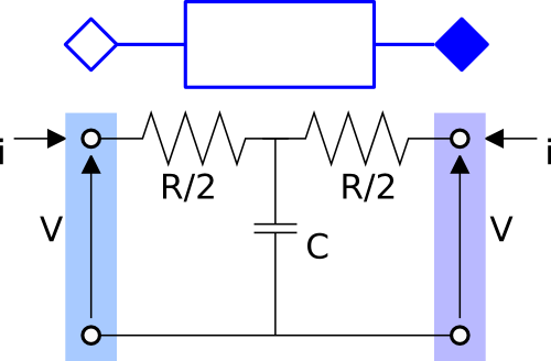
As can be seen in the figure, the resistance R is split in two halves
and the capacitance is located in the center.
The capacitance in the center is optional and can be selected using the
boolean flag use_C = true. The model is either dynamic or static depending on the
presence of the capacitive effect.
Parameters
| Type | Name | Default | Description |
|---|---|---|---|
| Boolean | useHeatPort (from ConditionalHeatPort) | false | = true, if heatPort is enabled |
| SI.Temperature | T (from ConditionalHeatPort) | 293.15 | Fixed device temperature if useHeatPort = false |
| Modelica.Units.SI.Resistance | R (from PartialTwoPortRLC) | Resistance at temperature T_ref | |
| Modelica.Units.SI.Temperature | T_ref (from PartialTwoPortRLC) | 298.15 | Reference temperature |
| Modelica.Units.SI.Temperature | M (from PartialTwoPortRLC) | 507.65 | Temperature constant (R_actual = R*(M + T_heatPort)/(M + T_ref)) |
| Modelica.Units.SI.Capacitance | C (from PartialTwoPortRLC) | Capacity | |
| Modelica.Units.SI.Inductance | L (from PartialTwoPortRLC) | Inductance | |
| Modelica.Units.SI.Voltage | Vc_start | V_nominal | Initial value of the voltage of the capacitance in the middle of the line |
| Nominal conditions | |||
| Modelica.Units.SI.Voltage | V_nominal (from PartialTwoPortRLC) | Nominal voltage (V_nominal >= 0) | |
| Model › Assumptions | |||
| Boolean | use_C | false | Set to true to add a capacitance in the center of the line |
Connectors
| Type | Name | Default | Description |
|---|---|---|---|
| Buildings.Electrical.Interfaces.BaseTerminal | terminal_n (from PartialBaseTwoPort) | Electric terminal side p | |
| Buildings.Electrical.Interfaces.BaseTerminal | terminal_p (from PartialBaseTwoPort) | Electric terminal side n | |
| Modelica.Thermal.HeatTransfer.Interfaces.HeatPort_a | heatPort (from ConditionalHeatPort) | Conditional heat port |
Components
| Type | Name | Default | Description |
|---|---|---|---|
| SI.Power | LossPower (from ConditionalHeatPort) | Loss power leaving component via heatPort | |
| SI.Temperature | T_heatPort (from ConditionalHeatPort) | Temperature of heatPort | |
| Modelica.Units.SI.Resistance | R_actual (from PartialTwoPortRLC) | Actual resistance = R*(M + T_heatPort)/(M + T_ref) | |
| Modelica.Units.SI.Voltage | Vc | Voltage of the capacitor |
Revisions
-
March 19, 2015, by Michael Wetter:
Removed redeclaration of phase system inTerminal_nandTerminal_pas it is already declared to the be the same phase system, and it is not declared to be replaceable. This avoids a translation error in OpenModelica. -
March 10, 2015, by Marco Bonvini:
Added initial equation and parameterVc_start. -
January 14, 2015, by Marco Bonvini:
Added equation that represents Joule losses -
June 2, 2014, by Marco Bonvini:
Revised documentation. -
October 31, 2013, by Marco Bonvini:
First implementation.