
modelSystem2
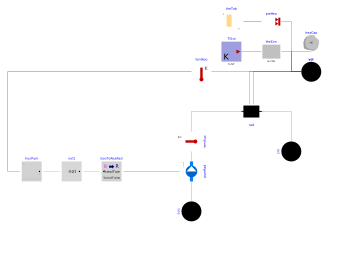
Extends from Modelica.Icons.Example (Icon for runnable examples).
Information
This part of the system model adds a radiator with a prescribed mass flow rate to the system that is implemented in Buildings.Examples.Tutorial.Boiler.System1.
Implementation
This model was built as follows:
-
First, we copied the model Buildings.Examples.Tutorial.Boiler.System1 and called it
Buildings.Examples.Tutorial.Boiler.System2. -
Since this model uses water as the medium, we declared the water medium model at the top-level of the model by adding the lines
replaceable package MediumW = Buildings.Media.Water "Medium model"; -
To model the pump, a temperature sensor which we will need later for the control, and a flow sink, we made instances of the models Buildings.Fluid.Movers.FlowControlled_m_flow (instance
pumRadfor the pump that serves the radiators), Buildings.Fluid.Sensors.TemperatureTwoPort (instancetemSup), Buildings.Fluid.HeatExchangers.Radiators.RadiatorEN442_2 (instancerad), and Buildings.Fluid.Sources.Boundary_pT (instancesouandsinfor the sink and source reservoirs, which will later be replace by the boiler loop).In all of these instances, we set the medium model to
MediumW. We also made an instance of the model Modelica.Thermal.HeatTransfer.Sensors.TemperatureSensor (instancetemRoo) to measure the room temperature. We connected the model as shown in the figure below.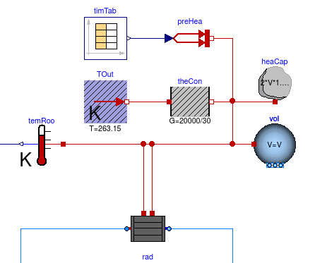
Note that there are two connections from the radiator to the room volume: One connection is for the convective heat flow rate, and the other is for the radiative heat flow rate. For simplicity, we assumed that the air and radiative temperature of the room are equal. Furthermore, we simplified the model by using only one radiator instead of multiple radiators, although this radiator will be quite large as it needs to provide a heat flow rate of 20 kW.
-
Next, we computed the design mass flow rate for the radiator. According to the schematic drawing, the radiator should have at the design conditions a supply water temperature of 50°C and a return water temperature of 40°C. Thus, we define the radiator mass flow rate as
parameter Modelica.Units.SI.HeatFlowRate Q_flow_nominal = 20000 "Nominal heat flow rate of radiator"; parameter Modelica.Units.SI.Temperature TRadSup_nominal = 273.15+50 "Radiator nominal supply water temperature"; parameter Modelica.Units.SI.Temperature TRadRet_nominal = 273.15+40 "Radiator nominal return water temperature"; parameter Modelica.Units.SI.MassFlowRate mRad_flow_nominal = Q_flow_nominal/4200/(TRadSup_nominal-TRadRet_nominal) "Radiator nominal mass flow rate"; -
Now, we set the mass flow rate of
pumRadandtemSuptomRad_flow_nominal. We also set the temperature of the fluid that flows out ofsoutoTRadSup_nominal. We configured the parameters of the radiator model asBuildings.Fluid.HeatExchangers.Radiators.RadiatorEN442_2 rad( redeclare package Medium = MediumW, energyDynamics=Modelica.Fluid.Types.Dynamics.FixedInitial, Q_flow_nominal=Q_flow_nominal, T_a_nominal=TRadSup_nominal, T_b_nominal=TRadRet_nominal) "Radiator";We configured the parameters of the pump model as
Buildings.Fluid.Movers.FlowControlled_m_flow pumRad( redeclare package Medium = MediumW, energyDynamics=Modelica.Fluid.Types.Dynamics.FixedInitial, m_flow_nominal=mRad_flow_nominal) "Pump for radiator"; -
To enable the pump when the room temperature is below 19°C and to switch it off when the room temperature is below 21°C, we implemented the control blocks as shown in the figure below.
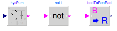
In this control sequence, the first block is a hysteresis element, which is modeled by Buildings.Controls.OBC.CDL.Reals.Hysteresis. It is configured as
  Buildings.Controls.OBC.CDL.Reals.Hysteresis hysPum(
    uLow=273.15 + 19,
    uHigh=273.15 + 21)
    "Pump hysteresis";
to output
falsewhen the input signal falls below 19°C, andtruewhen the input signal raises above 21°C. Next, we send the output to the instancenot1, which outputsy= not u
to negate the signal. The output of this signal is a boolean value, but the pump input signal is the required mass flow rate. Thus, we used the block Buildings.Controls.OBC.CDL.Conversions.BooleanToReal to convert the signal. We set the parameters of the boolean to real converter as
  Buildings.Controls.OBC.CDL.Conversions.BooleanToReal booToReaRad(
        realTrue=mRad_flow_nominal,
        realFalse=0) "Radiator pump signal";
For numerical reasons, in particular in large system models, it is recommended to continuously change the mass flow rate, as opposed to having a step change. Therefore, in the instance
pumRad, we leave the parameteruse_riseTimeat its default valuetrue. This will approximate a continuous change in mass flow rate when the pump is switched on or off. Finally, we closed the control loop between the room temperature sensor and the pump input signal.
This completes the initial version of the model. When simulating the model for 2 days, or 172800 seconds, the response shown below should be seen.
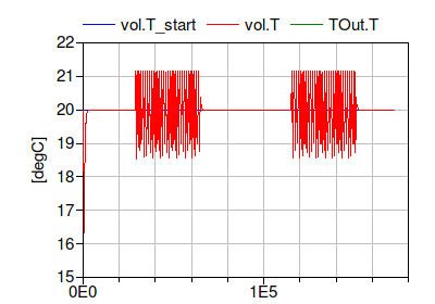
The figure shows that the room temperature is maintained at 20°C when the internal heat gain is zero, and controlled around 19°C to 21°C when there is an internal heat gain. The temperature is slightly outside this temperature range because of the time lag that is caused by the thermal capacity of the radiator.
Notes
For a more realistic model of a room, the model Buildings.ThermalZones.Detailed.MixedAir could have been used. For transient heat conduction, models from the package Buildings.HeatTransfer.Conduction could have been used.
Parameters
| Type | Name | Default | Description |
|---|---|---|---|
| Modelica.Units.SI.HeatFlowRate | Q_flow_nominal | 20000 | Nominal heat flow rate of radiator |
| Modelica.Units.SI.Temperature | TRadSup_nominal | 273.15 + 50 | Radiator nominal supply water temperature |
| Modelica.Units.SI.Temperature | TRadRet_nominal | 273.15 + 40 | Radiator nominal return water temperature |
| Modelica.Units.SI.MassFlowRate | mRad_flow_nominal | Q_flow_nominal/4200/(TRadSup_nominal - TRadRet_nominal) | Radiator nominal mass flow rate |
| Modelica.Units.SI.Volume | V | 6*10*3 | Room volume |
| Modelica.Units.SI.MassFlowRate | mA_flow_nominal | V*1.2*6/3600 | Nominal mass flow rate |
| Modelica.Units.SI.HeatFlowRate | QRooInt_flow | 4000 | Internal heat gains of the room |
Components
Contents
| Name | Description |
|---|---|
 MediumA MediumA | |
 MediumW MediumW | Medium model |
Revisions
-
April 9, 2024, by Hongxiang Fu:
SpecifiednominalValuesDefineDefaultPressureCurve=truein the mover component to suppress a warning. This is for #3819. -
March 6, 2017, by Michael Wetter:
Added missing density to computation of air mass flow rate.
This is for #673. -
December 22, 2014 by Michael Wetter:
RemovedModelica.Fluid.Systemto address issue #311. -
January 27, 2012, by Michael Wetter:
First implementation.