
modelSystem5
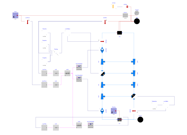
Extends from Modelica.Icons.Example (Icon for runnable examples).
Information
This part of the system model adds to the model that is implemented in Buildings.Examples.Tutorial.Boiler.System4 closed loop control for the valves.
Implementation
This model was built as follows:
-
First, we copied the model Buildings.Examples.Tutorial.Boiler.System4 and called it
Buildings.Examples.Tutorial.Boiler.System5. -
Next, we added closed loop control for the boiler valve as shown in the figure below.
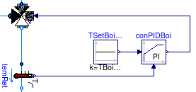
This is implemented using the constant block Buildings.Controls.OBC.CDL.Reals.Sources.Constant for the set point, the PID controller with output limitation Buildings.Controls.OBC.CDL.Reals.PID. We configured the controller as
  Buildings.Controls.OBC.CDL.Reals.PID conPIDBoi(
    controllerType=Buildings.Controls.OBC.CDL.Types.SimpleController.P,
    k=0.1,
    Ti=120,
    Td=1,
    reverseActing=false) "Controller for valve in boiler loop";
We set the proportional band to 10 Kelvin, hence
k=0.1. We set the integral time constant to 120 seconds, which is the same time as is required to open or close the valve. These settings turn out to give satisfactory closed loop control performance. Otherwise, we would need to retune the controller, which is usually easiest by configuring the controller as a P-controller, then tuning the proportional gain, and finally changing it to a PI-controller and tuning the integral time constant.Note that we also set
reverseActing=falsebecause if, for a constant set point, the measured temperature increases, the valve control signal needs to decrease towards y=0, because in this condition, the boiler inlet temperature is not yet high enough. Once it is high enough, the control error will be negative and the valve can open. -
The valve control for the radiator loop is implemented similar to the boiler loop, with the exception that the setpoint is computed using the model Buildings.Controls.OBC.CDL.Reals.Line to implement a set point that shifts as a function of the room temperature. This instance is called
TSetSupin the control sequence shown in the figure below, and takes as an input the room temperature, and the points for the (x1, f1) and (x2, f2) coordinates through which the setpoint goes.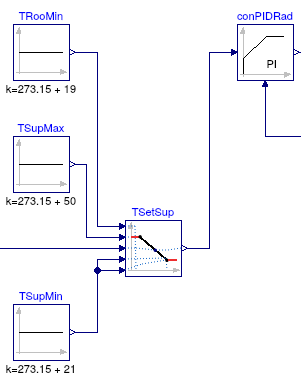
This completes the closed loop control. When simulating the model for 2 days, or 172800 seconds, the response shown below should be seen.
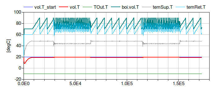
The figure shows that the return water temperature
temRet.T
quickly raises to 50°C and the supply water temperature
temSup.T
has smaller oscillations compared to
Buildings.Examples.Tutorial.Boiler.System4.
Parameters
| Type | Name | Default | Description |
|---|---|---|---|
| Modelica.Units.SI.HeatFlowRate | Q_flow_nominal | 20000 | Nominal heat flow rate of radiator |
| Modelica.Units.SI.Temperature | TRadSup_nominal | 273.15 + 50 | Radiator nominal supply water temperature |
| Modelica.Units.SI.Temperature | TRadRet_nominal | 273.15 + 40 | Radiator nominal return water temperature |
| Modelica.Units.SI.MassFlowRate | mRad_flow_nominal | Q_flow_nominal/4200/(TRadSup_nominal - TRadRet_nominal) | Radiator nominal mass flow rate |
| Modelica.Units.SI.Temperature | TBoiSup_nominal | 273.15 + 70 | Boiler nominal supply water temperature |
| Modelica.Units.SI.Temperature | TBoiRet_min | 273.15 + 60 | Boiler minimum return water temperature |
| Modelica.Units.SI.MassFlowRate | mBoi_flow_nominal | Q_flow_nominal/4200/(TBoiSup_nominal - TBoiRet_min) | Boiler nominal mass flow rate |
| Modelica.Units.SI.MassFlowRate | mRadVal_flow_nominal | Q_flow_nominal/4200/(TBoiSup_nominal - TRadRet_nominal) | Radiator nominal mass flow rate |
| Modelica.Units.SI.Volume | V | 6*10*3 | Room volume |
| Modelica.Units.SI.MassFlowRate | mA_flow_nominal | V*1.2*6/3600 | Nominal mass flow rate |
| Modelica.Units.SI.HeatFlowRate | QRooInt_flow | 4000 | Internal heat gains of the room |
Components
Contents
| Name | Description |
|---|---|
 MediumA MediumA | |
 MediumW MediumW | Medium model |
Revisions
-
October 14, 2026, by Michael Wetter:
Added prescribed temperature model for boiler heat loss.
This is for #4775. -
April 9, 2024, by Hongxiang Fu:
SpecifiednominalValuesDefineDefaultPressureCurve=truein the mover component to suppress a warning. This is for #3819. -
March 6, 2017, by Michael Wetter:
Added missing density to computation of air mass flow rate.
This is for #673. -
July 2, 2015, by Michael Wetter:
Changed control input forconPIDBoiand setreverseActing=falseto address issue #436. -
December 22, 2014 by Michael Wetter:
RemovedModelica.Fluid.Systemto address issue #311. -
March 1, 2013, by Michael Wetter:
Added nominal pressure drop for valves as this parameter no longer has a default value. -
January 27, 2012, by Michael Wetter:
First implementation.