modelEnergyConversionWarmUp
Extends from Modelica.Blocks.Icons.Block (Basic graphical layout of input/output block).
Information
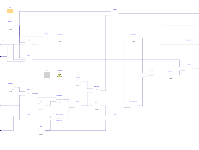
The model defines energy conversion for the warm-up mode that is dependent on the engine temperature (e.g. CHPs with Stirling engines). The engine fuel flow rate is a function of the fuel flow rate at the maximum power output, as well as the difference between the nominal engine temperature and the actual engine temperature. Energy conversion from fuel to the electric power and heat is modeled using system's part-load electrical and thermal efficiencies, based on the empirical data from the manufacturer. The curves are described by a fifth order polynomial, a function of the electric power, water flow rate and water inlet temperature. The air flow rate is modeled using a second order polynomial, a function of the fuel flow rate.
Parameters
| Type | Name | Default | Description |
|---|---|---|---|
| Buildings.Fluid.CHPs.Data.Generic | per | Performance data |
Connectors
| Type | Name | Default | Description |
|---|---|---|---|
| Buildings.Controls.OBC.CDL.Interfaces.RealInput | mWat_flow | Water mass flow rate | |
| Buildings.Controls.OBC.CDL.Interfaces.RealInput | TWatIn | Water inlet temperature | |
| Buildings.Controls.OBC.CDL.Interfaces.RealInput | TRoo | Room temperature | |
| Buildings.Controls.OBC.CDL.Interfaces.RealInput | TEng | Engine temperature | |
| Buildings.Controls.OBC.CDL.Interfaces.RealOutput | PEleNet | Electric power generation | |
| Buildings.Controls.OBC.CDL.Interfaces.RealOutput | mFue_flow | Fuel mass flow rate | |
| Buildings.Controls.OBC.CDL.Interfaces.RealOutput | mAir_flow | Air mass flow rate | |
| Buildings.Controls.OBC.CDL.Interfaces.RealOutput | QGen_flow | Heat generation rate within the engine |
Revisions
-
June 1, 2019, by Tea Zakula:
First implementation.