
modelVariableSpeedEnergyPlusPartLoad
Extends from Modelica.Icons.Example (Icon for runnable examples).
Information
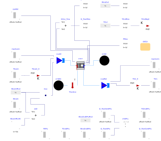
This model validates the model Buildings.Fluid.DXSystems.Cooling.WaterSource.VariableSpeed.
The difference in results of TOut and XOut at the beginning and end of the simulation is because the mass flow rate is zero. For zero mass flow rate, EnergyPlus assumes steady state condition, whereas the Modelica model is a dynamic model and hence the properties at the outlet are equal to the state variables of the model.
The EnergyPlus results were generated using the example file ZoneVSWSHP_wDOAS.idf
from EnergyPlus 7.1,
with a nominal cooling capacity of 6758 Watts instead of autosizing and an internal gain from
electric equipment as 6000 Watts.This allowed to have a speed ratio between 0 and 1.
Note that EnergyPlus mass fractions (X) are in mass of water vapor per mass of dry air,
whereas Modelica uses the total mass as a reference. Hence, the EnergyPlus values
are corrected by dividing them by
1+X.
Parameters
| Type | Name | Default | Description |
|---|---|---|---|
| Modelica.Units.SI.Power | Q_flow_nominal | datCoi.sta[1].nomVal.Q_flow_nominal | Nominal power |
| Modelica.Units.SI.MassFlowRate | m_flow_nominal | datCoi.sta[1].nomVal.m_flow_nominal | Nominal mass flow rate |
| Modelica.Units.SI.PressureDifference | dpEva_nominal | 1000 | Pressure drop at m_flow_nominal |
| Modelica.Units.SI.PressureDifference | dpCon_nominal | 40000 | Pressure drop at mCon_flow_nominal |
| Buildings.Fluid.DXSystems.Cooling.WaterSource.Data.Generic.DXCoil | datCoi | Coil data |
Components
| Type | Name | Default | Description |
|---|---|---|---|
| WaterSource.VariableSpeed | varSpeDX | Variable speed DX coil | |
| Modelica.Blocks.Sources.TimeTable | speRat | EnergyPlus speed ratio for this model | |
| Modelica.Blocks.Sources.TimeTable | TCIn | Condenser inlet temperature | |
| Modelica.Blocks.Sources.TimeTable | TEvaIn | Coil inlet temperature | |
| Modelica.Blocks.Sources.TimeTable | XEvaIn | Water fraction of moist air | |
| Modelica.Blocks.Routing.Multiplex2 | mux | Converts in an array | |
| Buildings.Utilities.IO.BCVTB.From_degC | TCIn_K | Converts degC to K | |
| Buildings.Utilities.IO.BCVTB.From_degC | TEvaIn_K | Converts degC to K | |
| Modelica.Blocks.Math.Mean | TOutMea | ||
| Buildings.Utilities.IO.BCVTB.To_degC | TOutDegC | ||
| Modelica.Blocks.Sources.RealExpression | TOut | ||
| Modelica.Blocks.Math.Mean | XEvaOutMea | ||
| Modelica.Blocks.Sources.RealExpression | XEvaOut | ||
| Modelica.Blocks.Math.Mean | Q_flowMea | Mean of cooling rate | |
| Modelica.Blocks.Math.Mean | Q_flowSenMea | Mean of sensible cooling rate | |
| Modelica.Blocks.Math.Mean | PMea | Mean of power | |
| Modelica.Blocks.Math.Add | add | ||
| Modelica.Blocks.Sources.Constant | XEvaInMoiAir | Moist air fraction = 1 | |
| Modelica.Blocks.Sources.TimeTable | TOutEPlu | EnergyPlus result: outlet temperature | |
| Modelica.Blocks.Sources.TimeTable | Q_flowEPlu | EnergyPlus result: heat flow | |
| Modelica.Blocks.Sources.TimeTable | Q_flowSenEPlu | EnergyPlus result: sensible heat flow | |
| Modelica.Blocks.Math.Division | shrEPlu | EnergyPlus result: SHR | |
| Modelica.Blocks.Sources.TimeTable | XEvaOutEPlu | EnergyPlus result: outlet water mass fraction | |
| Modelica.Blocks.Sources.TimeTable | PEPlu | EnergyPlus result: electric power | |
| Modelica.Blocks.Sources.RealExpression | XEvaInMod | Modified XEvaIn | |
| Modelica.Blocks.Sources.RealExpression | XEvaOutEPluMod | Modified XEvaOut of energyPlus to comapre with the model results | |
| Modelica.Blocks.Math.Add | QCoo_flow | Total cooling heat flow rate | |
| Sources.MassFlowSource_T | souAir | Source on air side | |
| Sources.Boundary_pT | sinAir | Sink on air side | |
| Sources.Boundary_pT | sinWat | Sink on water side | |
| Sources.MassFlowSource_T | souWat | Source on water side | |
| Modelica.Blocks.Sources.TimeTable | masEvaIn | Mass flowrate at the evaporator | |
| Modelica.Blocks.Sources.TimeTable | masConIn | Mass flowrate at the condenser | |
| Sensors.TemperatureTwoPort | TConOut | Outlet temperature at the condenser | |
| Modelica.Blocks.Sources.TimeTable | TCOutEPlu | Condenser outlet temperature | |
| Modelica.Blocks.Sources.TimeTable | Q_flowConEPlu | Condenser heat flow |
Contents
| Name | Description |
|---|---|
 MediumAir MediumAir | Medium model for air |
 MediumWater MediumWater | Medium model for water |
Revisions
-
February 16, 2017 by Yangyang Fu:
First implementation.