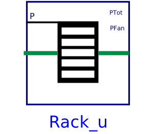
modelRack_u
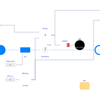
Extends from Buildings.Fluid.DataCenterEquipment.Racks.BaseClasses.PartialRack (Partial model of an IT rack, with utilization as input).
Information
Model of an air-cooled IT rack.
Electrical and fluid characterization
The model takes as a parameter the thermal design power (TDB) P_nominal
and as an input the utilization u.
The heat added to the coolant fluid is then calculated as
Q_flow = u P_nominal.
The fluid outlet temperature is computed using a first order delay to mimic
the transient effect. This first order delay is characterized by the user-configurable
time constant tau, set by default to tau=2 seconds.
For exact transient response, this value should be identified based on measurements.
To compute the pressure drop, the model uses Buildings.Fluid.FixedResistances.PressureDrop. Therefore, the mass flow rate and pressure drop are related as
m_flow ⁄ m_flow_nominal = (dp ⁄ dp_nominal)m,
where
m_flow_nominal is a parameter for the design flow rate,
dp is the pressure difference between inlet and outlet,
dp_nominal is a parameter for the design pressure difference, and
m is a parameter for the flow exponent.
Fan mass flow rate
The model has a built-in fan, configured to have zero back pressure.
The fan has an ideal controller that maintains a temperature difference across
the rack equal to the parameter dTSet, before adding the fan
energy to that air stream.
Note that therefore, the actual rack outlet temperature is slightly higher because the
fan energy is not included in the calculation of the mass flow rate.
If it were included, the model would have a nonlinear system of equations,
or would require a PI controller.
Parameters
| Type | Name | Default | Description |
|---|---|---|---|
| Buildings.Fluid.DataCenterEquipment.Racks.BaseClasses.Data.Generic | dat (from PartialRack) | Performance data | |
| Assumptions | |||
| Boolean | allowFlowReversal (from PartialTwoPort) | true | = false to simplify equations, assuming, but not enforcing, no flow reversal |
| Dynamics › Conservation equations | |||
| Modelica.Fluid.Types.Dynamics | energyDynamics (from PartialRack) | Modelica.Fluid.Types.Dynamics.DynamicFreeInitial | Type of energy balance: dynamic (3 initialization options) or steady state |
| Dynamics | |||
| Modelica.Units.SI.Time | tau (from PartialRack) | 2 | Time constant of fluid outlet temperature at nominal flow |
| Initialization | |||
| Medium.Temperature | T_start (from PartialRack) | Medium.T_default | Start value of temperature |
Connectors
| Type | Name | Default | Description |
|---|---|---|---|
| Modelica.Fluid.Interfaces.FluidPort_a | port_a (from PartialTwoPort) | Fluid connector a (positive design flow direction is from port_a to port_b) | |
| Modelica.Fluid.Interfaces.FluidPort_b | port_b (from PartialTwoPort) | Fluid connector b (positive design flow direction is from port_a to port_b) | |
| Modelica.Blocks.Interfaces.RealInput | P (from PartialRack) | Electrical power consumption | |
| Modelica.Blocks.Interfaces.RealOutput | PTot | Electrical power consumed by IT and fan | |
| Modelica.Blocks.Interfaces.RealOutput | PFan | Electrical power consumed by fan |
Components
| Type | Name | Default | Description |
|---|---|---|---|
| Real | utiIT (from PartialRack) | P/dat.PIT_nominal | IT utilization |
| Fluid.Delays.DelayFirstOrder | vol (from PartialRack) | Fluid control volume | |
| Modelica.Units.SI.MassFlowRate | m_flow (from PartialRack) | port_a.m_flow | Mass flow rate from port_a to port_b |
| Fluid.Movers.BaseClasses.IdealSource | fan | Mass flow source | |
| Fluid.Sensors.VolumeFlowRate | senVolFlo | Volume flow rate | |
| Buildings.Controls.OBC.CDL.Reals.MultiplyByParameter | PEleFan | Electricity use of fan |
Revisions
-
June 26, 2026, by Michael Wetter:
First implementation.