modelColdPlateR_P
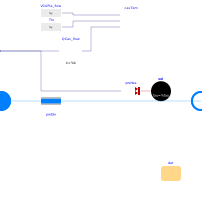
Extends from Buildings.Fluid.DataCenterEquipment.Racks.BaseClasses.PartialRack (Partial model of an IT rack, with utilization as input).
Information
Model of IT racks with cold plate heat exchangers based on the characterization of the Open Compute Project.
Electrical and fluid characterization
The model takes as an input the electrical power conumption P
and adds it as heat added to the coolant fluid
Q_flow = P.
The fluid outlet temperature is computed using a first order delay to mimic
the transient effect. This first order delay is characterized by the user-configurable
time constant tau, set by default to tau=2 seconds.
For exact transient response, this value should be identified based on measurements.
To compute the pressure drop, the model uses Buildings.Fluid.FixedResistances.PressureDrop. Therefore, the mass flow rate and pressure drop are related as
m_flow ⁄ m_flow_nominal = (dp ⁄ dp_nominal)m,
where
m_flow_nominal is a parameter for the design flow rate,
dp is the pressure difference between inlet and outlet,
dp_nominal is a parameter for the design pressure difference, and
m is a parameter for the flow exponent.
Based on a data fit using the data in Chen et al., (2024), the default value is m=1.85.
The model assumes a default pressure drop dp_nominal of
dp_nominal=50 kPa, which is the pressure drop of the OCP specified
cold plate with a 8x1 loop at 10 l/min flow rate with 25% PGW.
Case temperature
The model also computes the case temperature, which is the external surface temperature of the component's packaging, typically the top-center point where a thermal interface material or heat sink is attached.
The case temperature is computed based on the coolant inlet temperature and the heat dissipated by the chip, using the case-to-inlet thermal resistance of a cold plate. Thefore, the model assumes sufficient mass flow rate, e.g., this model simplifies the case temperature as being independent of the coolant mass flow rate, other than through the variation of the thermal resistance on that mass flow rate. This follows the convention used in the Open Compute Project report by Chen et al. (2023), which uses for the case-to-inlet thermal resistance the definition
R = (T_cas - T_inlet) ⁄ Q_flow,
where
T_cas is the case temperature,
T_inlet is the coolant inlet temperature and
Q_flow is the heat emitted by the cold plate.
Use of this equation requires knowledge of the heat flow rate of one cold plate Q_flow,
but the component model takes as a parameter the total design heat flow rate PIT_nominal.
The model approximates the number of cold plates using
n_col = PIT_nominal / (VColPla_flow_nominal * rho * c_p * dT_nominal),
where
VColPla_flow_nominal is the design flow rate of a cold plate, approximated by default as the average
value of the data record's volume flow rate, VColPla_flow_nominal = average(datRes.V_flow),
rho is the fluid density,
c_p is the fluid specific heat capacity, and
dT_nominal is the design temperature difference.
This thermal resistance is computed using the data from the data record
Buildings.Fluid.DataCenterEquipment.Racks.LiquidCooledSinglePhase.Data.Generic_R_m_flow.
The computation is done in the block casTem,
which does a data fit for R. The relative error of this data fit
is shown in casTem.relErrR.
References
Cheng Chen, Dennis Trieu, Tejas Shah, Allen Guo, Jaylen Cheng, Christopher Chapman, Sukhvinder Kang, Eran Dagan, Assaf Dinstag,Jane Yao. OCP OAI SYSTEM LIQUID COOLING GUIDELINES. 2023.
Parameters
| Type | Name | Default | Description |
|---|---|---|---|
| Buildings.Fluid.DataCenterEquipment.Racks.BaseClasses.Data.Generic | dat (from PartialRack) | Performance data | |
| Assumptions | |||
| Boolean | allowFlowReversal (from PartialTwoPort) | true | = false to simplify equations, assuming, but not enforcing, no flow reversal |
| Dynamics › Conservation equations | |||
| Modelica.Fluid.Types.Dynamics | energyDynamics (from PartialRack) | Modelica.Fluid.Types.Dynamics.DynamicFreeInitial | Type of energy balance: dynamic (3 initialization options) or steady state |
| Dynamics | |||
| Modelica.Units.SI.Time | tau (from PartialRack) | 2 | Time constant of fluid outlet temperature at nominal flow |
| Initialization | |||
| Medium.Temperature | T_start (from PartialRack) | Medium.T_default | Start value of temperature |
| Case temperature | |||
| Modelica.Units.SI.TemperatureDifference | dT_nominal | dat.PIT_nominal/(dat.m_flow_nominal*cp_default) | Design temperature differences, used to compute cold plate temperature |
| Modelica.Units.SI.VolumeFlowRate | VColPla_flow_nominal | sum(dat.theRes.V_flow)/size(dat.theRes.V_flow, 1) | Design flow rate of one cold plate, used to compute the case temperature |
| Real | nColPla | dat.PIT_nominal/(VColPla_flow_nominal*d_default*cp_default*dT_nominal) | Number of cold plates, used to compute the case temperature |
| Advanced | |||
| Boolean | linearized | false | = true, use linear relation between m_flow and dp for any flow rate |
Connectors
| Type | Name | Default | Description |
|---|---|---|---|
| Modelica.Fluid.Interfaces.FluidPort_a | port_a (from PartialTwoPort) | Fluid connector a (positive design flow direction is from port_a to port_b) | |
| Modelica.Fluid.Interfaces.FluidPort_b | port_b (from PartialTwoPort) | Fluid connector b (positive design flow direction is from port_a to port_b) | |
| Modelica.Blocks.Interfaces.RealInput | P (from PartialRack) | Electrical power consumption |
Components
| Type | Name | Default | Description |
|---|---|---|---|
| Real | utiIT (from PartialRack) | P/dat.PIT_nominal | IT utilization |
| Fluid.Delays.DelayFirstOrder | vol (from PartialRack) | Fluid control volume | |
| Modelica.Units.SI.MassFlowRate | m_flow (from PartialRack) | port_a.m_flow | Mass flow rate from port_a to port_b |
| Modelica.Units.SI.PressureDifference | dp | preDro.dp | Pressure difference between port_a and port_b |
| Buildings.Fluid.DataCenterEquipment.Racks.LiquidCooledSinglePhase.BaseClasses.CaseTemperature | casTem | Case temperature |
Revisions
-
December 16, 2025, by Michael Wetter:
First implementation.