functionsingleUTubeResistances
Information
This model computes the thermal resistances of a single-U-tube borehole using the method of Bauer et al. (2011). It also computes the fluid-to-ground thermal resistance Rb and the grout-to-grout thermal resistance Ra as defined by Hellstroem (1991) using the multipole method.
The figure below shows the thermal network set up by Bauer et al. (2011).
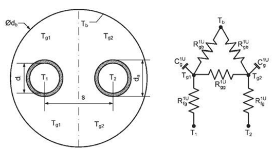
The different resistances are calculated as follows. The grout zone and bore hole wall thermal resistance are related as
Rgb1U = ( 1 - x1U ) Rg1U.
The thermal resistance between the two grout zones are
Rgg1U = 2 Rgb1U ( Rar1U - 2 x1U Rg1U ) / ( 2 Rgb1U - Rar1U + 2 x1U Rg1U ).
Thermal resistance between the pipe wall to the capacity in the grout is
RCondGro = x1U Rg1U + log ( ( rTub + eTub ) /rTub ) / ( 2 π hSeg kTub ).
The capacities are located at
x1U =log ( (rBor2 + 2 ( rTub + eTub ) 2)1⁄2/ ( 2 ( rTub + eTub ) ) ) / log ( rBor/ ( √2 ( rTub + eTub ))).
The thermal resistance between the outer borehole wall and one tube is
Rg1U =2 Rb ⁄ hSeg.
The thermal resistance between the two pipe outer walls is
Rar1U =Ra ⁄ hSeg.
The fluid to ground thermal resistance Rb and the grout to grout thermal resistance Ra are calculated with the multipole method (Hellstroem (1991)) as
Rb =1/ ( 4 π kFil ) ( log ( rBor/ ( rTub + eTub ) ) + log ( rBor/ ( 2 xC ) ) + σ log ( rBor4/ ( rBor4 - xC4 ) ) ) - 1/ ( 4 π kFil ) ( ( rTub + eTub ) 2/ ( 4 xC2 ) ( 1 - σ 4 xC4/ ( rBor4 - xC4 ) ) 2 ) / ( ( 1 + β ) / ( 1 - β ) + ( rTub + eTub ) 2/ ( 4 xC2 ) ( 1 + σ 16 xC4 rBor4/ ( rBor4 - xC4 ) 2)).
Ra = 1/ ( π kFil ) ( log ( 2 xC/rTub ) + σ log (( rBor2 + xC2 ) / ( rBor2 - xC2 ) ) ) - 1/ ( π kFil ) ( rTub2/ ( 4 xC2 ) ( 1 + σ 4 rBor4 xC2/ ( rBor4 - xC4 ) ) / ( ( 1 + β ) / ( 1 - β ) - rTub2/ ( 4 xC2 ) + σ 2 rTub2 rBor2 ( rBor4 + xC4 ) / ( rBor4 - xC4 ) 2)),
with σ = ( kFil - kSoi ) / ( kFil + kSoi ) and β = 2 π kFil RCondPipe, where kFil and kSoi are the conductivity of the filling material and of the ground, rTub+eTub and rBor are the pipe and the borehole outside radius and xC is the shank spacing, which is equal to the distance between the center of borehole and the center of the pipe.
Note: The value of Rgg1U may be negative as long as
1/Rgg1U + 1/(2 Rgb1U) > 0,
in which case the laws of thermodynamics are not violated. See Bauer et al. (2011) for details.
References
G. Hellström. Ground heat storage: thermal analyses of duct storage systems (Theory). Dept. of Mathematical Physics, University of Lund, Sweden, 1991.
D. Bauer, W. Heidemann, H. Müller-Steinhagen, and H.-J. G. Diersch. Thermal resistance and capacity models for borehole heat exchangers . International Journal Of Energy Research, 35:312–320, 2011.
Inputs
| Type | Name | Default | Description |
|---|---|---|---|
| Modelica.Units.SI.Height | hSeg | Height of the element | |
| Modelica.Units.SI.Radius | rBor | Radius of the borehole | |
| Modelica.Units.SI.Radius | rTub | Radius of the tube | |
| Modelica.Units.SI.Length | eTub | Thickness of the tubes | |
| Modelica.Units.SI.Length | xC | Shank spacing, defined as the distance between the center of a pipe and the center of the borehole | |
| Modelica.Units.SI.ThermalConductivity | kSoi | Thermal conductivity of the soi | |
| Modelica.Units.SI.ThermalConductivity | kFil | Thermal conductivity of the grout | |
| Modelica.Units.SI.ThermalConductivity | kTub | Thermal conductivity of the tube |
Outputs
| Type | Name | Default | Description |
|---|---|---|---|
| Modelica.Units.SI.ThermalResistance | Rgb | Thermal resistance between the grout zone and the borehole wall | |
| Modelica.Units.SI.ThermalResistance | Rgg | Thermal resistance between the two grout zones | |
| Modelica.Units.SI.ThermalResistance | RCondGro | Thermal resistance between the pipe wall ant the capacity in the grout | |
| Real | x | Capacity location |
Revisions
-
January 21, 2015 by Michael Wetter:
Fixed bug inbetabeing used before it was assigned. -
February 14, 2014 by Michael Wetter:
Added an assert statement to test for non-physical values. -
February 13, 2014 by Damien Picard:
Edit documentation and add formula for beta. -
February 12, 2014, by Damien Picard:
Remove the flow dependency of the resistances, as this function calculates the conduction resistances only. -
January 24, 2014, by Michael Wetter:
Revised implementation. -
January 23, 2014, by Damien Picard:
First implementation.