blockDryCooler
Model for thermal performance of dry cooling tower
Extends from Modelica.Blocks.Icons.Block (Basic graphical layout of input/output block).
Information
Model for the thermal performance of the dry cooling tower.
The air mass flow rate is computed as
ṁair = y ṁair,nominal
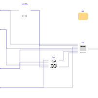
This air flow rate is supplied to both the heat transfer coefficient block
Buildings.Fluid.HeatExchangers.BaseClasses.HADryCoil
(instance hA)
and to
Buildings.Fluid.HeatExchangers.CoolingTowers.BaseClasses.DryCoolerUA
(instance dryCoolerUA), which computes the overall thermal
conductance UA, the effectiveness ε, and the
heat flow rate Q̇.
For the full documentation, see Buildings.Fluid.HeatExchangers.CoolingTowers.DryCooler.
Parameters
| Type | Name | Default | Description |
|---|---|---|---|
| Buildings.Fluid.HeatExchangers.CoolingTowers.Data.DryCooler.Generic | dat | Performance data record | |
| Modelica.Units.SI.ThermalConductance | UA_nominal | UA.UA_nominal | Thermal conductance at nominal flow, used to compute heat capacity |
| Real | eps_nominal | UA.eps_nominal | Nominal heat transfer effectiveness |
| Real | NTU_nominal | UA.NTU_nominal | Nominal number of transfer units |
| Nominal condition | |||
| Modelica.Units.SI.MassFlowRate | m_flow_nominal | Nominal mass flow rate of water | |
| Fan | |||
| Modelica.Units.SI.MassFlowRate | mAir_flow_nominal | m_flow_nominal/dat.ratCooAir_nominal | Nominal mass flow rate of air |
| Real | yMin | Minimum control signal until fan is switched off (used for smoothing between forced and free convection regime) | |
Connectors
| Type | Name | Default | Description |
|---|---|---|---|
| Modelica.Blocks.Interfaces.RealInput | y | Fan control signal | |
| Modelica.Blocks.Interfaces.RealInput | m_flow | Cooling fluid mass flow rate | |
| Modelica.Blocks.Interfaces.RealInput | TCooIn | Inlet water temperature | |
| Modelica.Blocks.Interfaces.RealInput | TDryBul | Entering air dry bulb temperature | |
| Modelica.Blocks.Interfaces.RealOutput | Q_flow | Heat removed from water |
Contents
| Name | Description |
|---|---|
 Medium Medium | Medium in the component |
Revisions
-
April 27, 2026, by Michael Wetter:
First implementation.