modelDryCoilCounterFlow
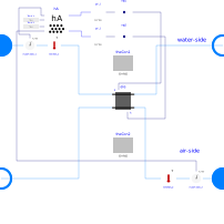
Extends from Buildings.Fluid.Interfaces.PartialFourPortInterface (Partial model with four ports and declaration of quantities that are used by many models), Buildings.Fluid.Interfaces.FourPortFlowResistanceParameters (Parameters for flow resistance for models with four ports).
Information
Model of a discretized coil without water vapor condensation.
The coil consists of two flow paths which are, at the design flow direction,
in opposite direction to model a counterflow heat exchanger.
The flow paths are discretized into nEle elements.
Each element is modeled by an instance of
Buildings.Fluid.HeatExchangers.BaseClasses.HexElementSensible.
Each element has a state variable for the metal.
The convective heat transfer coefficients can, for each fluid individually, be computed as a function of the flow rate and/or the temperature, or assigned to a constant. This computation is done using an instance of Buildings.Fluid.HeatExchangers.BaseClasses.HADryCoil.
To model humidity condensation, use the model Buildings.Fluid.HeatExchangers.WetCoilCounterFlow instead of this model, as this model computes only sensible heat transfer.
Implementation
At very small flow rates, which may be caused when the fan is off but there is wind pressure
on the building that entrains outside air through the HVAC system, large temperature differences
could occur if diffusion were neglected.
This model therefore approximates a small diffusion between the elements to have more uniform
medium temperatures if the flow is near zero.
The approximation is done using the heat conductors heaCon1 and heaCon2.
As this is a rough approximation, neighboring elements are connected through these heat conduction
elements, ignoring the actual geometrical configuration.
Also, radiation between the coil surfaces on the air side is not modelled explicitly, but
rather may be considered as approximated by these heat conductors.
Parameters
| Type | Name | Default | Description |
|---|---|---|---|
| Assumptions | |||
| Boolean | allowFlowReversal1 (from PartialFourPort) | true | = false to simplify equations, assuming, but not enforcing, no flow reversal for medium 1 |
| Boolean | allowFlowReversal2 (from PartialFourPort) | true | = false to simplify equations, assuming, but not enforcing, no flow reversal for medium 2 |
| Nominal condition | |||
| Modelica.Units.SI.MassFlowRate | m1_flow_nominal (from PartialFourPortInterface) | Nominal mass flow rate | |
| Modelica.Units.SI.MassFlowRate | m2_flow_nominal (from PartialFourPortInterface) | Nominal mass flow rate | |
| Modelica.Units.SI.PressureDifference | dp1_nominal (from FourPortFlowResistanceParameters) | Pressure difference | |
| Modelica.Units.SI.PressureDifference | dp2_nominal (from FourPortFlowResistanceParameters) | Pressure difference | |
| Advanced | |||
| Medium1.MassFlowRate | m1_flow_small (from PartialFourPortInterface) | 1E-4*abs(m1_flow_nominal) | Small mass flow rate for regularization of zero flow |
| Medium2.MassFlowRate | m2_flow_small (from PartialFourPortInterface) | 1E-4*abs(m2_flow_nominal) | Small mass flow rate for regularization of zero flow |
| Advanced › Diagnostics | |||
| Boolean | show_T (from PartialFourPortInterface) | false | = true, if actual temperature at port is computed |
| Flow resistance › Medium 1 | |||
| Boolean | computeFlowResistance1 (from FourPortFlowResistanceParameters) | true | =true, compute flow resistance. Set to false to assume no friction |
| Boolean | from_dp1 (from FourPortFlowResistanceParameters) | false | = true, use m_flow = f(dp) else dp = f(m_flow) |
| Real | n1 (from FourPortFlowResistanceParameters) | 2 | Flow exponent for side 1, n=1 for laminar, n=2 for turbulent |
| Boolean | linearizeFlowResistance1 (from FourPortFlowResistanceParameters) | false | = true, use linear relation between m_flow and dp for any flow rate |
| Real | deltaM1 (from FourPortFlowResistanceParameters) | 0.1 | Fraction of nominal flow rate where flow transitions to laminar |
| Flow resistance › Medium 2 | |||
| Boolean | computeFlowResistance2 (from FourPortFlowResistanceParameters) | true | =true, compute flow resistance. Set to false to assume no friction |
| Boolean | from_dp2 (from FourPortFlowResistanceParameters) | false | = true, use m_flow = f(dp) else dp = f(m_flow) |
| Real | n2 (from FourPortFlowResistanceParameters) | 2 | Flow exponent for side 2, n=1 for laminar, n=2 for turbulent |
| Boolean | linearizeFlowResistance2 (from FourPortFlowResistanceParameters) | false | = true, use linear relation between m_flow and dp for any flow rate |
| Real | deltaM2 (from FourPortFlowResistanceParameters) | 0.1 | Fraction of nominal flow rate where flow transitions to laminar |
| General › Nominal condition | |||
| Modelica.Units.SI.ThermalConductance | UA_nominal | Thermal conductance at nominal flow, used to compute heat capacity | |
| Geometry | |||
| Integer | nEle | 4 | Number of pipe segments used for discretization |
| Dynamics › Conservation equations | |||
| Modelica.Fluid.Types.Dynamics | energyDynamics | Modelica.Fluid.Types.Dynamics.DynamicFreeInitial | Formulation of energy balance |
| Modelica.Units.SI.Time | tau1 | 10 | Time constant at nominal flow for medium 1 |
| Modelica.Units.SI.Time | tau2 | 2 | Time constant at nominal flow for medium 2 |
| Modelica.Units.SI.Time | tau_m | 5 | Time constant of metal at nominal UA value |
| Heat transfer | |||
| Boolean | waterSideFlowDependent | true | Set to false to make water-side hA independent of mass flow rate |
| Boolean | airSideFlowDependent | true | Set to false to make air-side hA independent of mass flow rate |
| Boolean | waterSideTemperatureDependent | false | Set to false to make water-side hA independent of temperature |
| Boolean | airSideTemperatureDependent | false | Set to false to make air-side hA independent of temperature |
| Real | n_w | 0.85 | Water-side exponent for convective heat transfer coefficient, h~m_flow^n_w |
| Real | n_a | 0.8 | Air-side exponent for convective heat transfer coefficient, h~m_flow^n_a |
| Heat transfer › Nominal condition | |||
| Real | r_nominal | 2/3 | Ratio between air-side and water-side convective heat transfer coefficient |
| Experimental | |||
| Modelica.Units.SI.ThermalConductance | GDif | 1E-2*UA_nominal/max(1, (nEle - 1)) | Thermal conductance to approximate diffusion (which improves model at near-zero flow rates) |
Connectors
| Type | Name | Default | Description |
|---|---|---|---|
| Modelica.Fluid.Interfaces.FluidPort_a | port_a1 (from PartialFourPort) | Fluid connector a1 (positive design flow direction is from port_a1 to port_b1) | |
| Modelica.Fluid.Interfaces.FluidPort_b | port_b1 (from PartialFourPort) | Fluid connector b1 (positive design flow direction is from port_a1 to port_b1) | |
| Modelica.Fluid.Interfaces.FluidPort_a | port_a2 (from PartialFourPort) | Fluid connector a2 (positive design flow direction is from port_a2 to port_b2) | |
| Modelica.Fluid.Interfaces.FluidPort_b | port_b2 (from PartialFourPort) | Fluid connector b2 (positive design flow direction is from port_a2 to port_b2) |
Components
| Type | Name | Default | Description |
|---|---|---|---|
| Medium1.MassFlowRate | m1_flow (from PartialFourPortInterface) | port_a1.m_flow | Mass flow rate from port_a1 to port_b1 (m1_flow > 0 is design flow direction) |
| Modelica.Units.SI.PressureDifference | dp1 (from PartialFourPortInterface) | port_a1.p - port_b1.p | Pressure difference between port_a1 and port_b1 |
| Medium2.MassFlowRate | m2_flow (from PartialFourPortInterface) | port_a2.m_flow | Mass flow rate from port_a2 to port_b2 (m2_flow > 0 is design flow direction) |
| Modelica.Units.SI.PressureDifference | dp2 (from PartialFourPortInterface) | port_a2.p - port_b2.p | Pressure difference between port_a2 and port_b2 |
| Medium1.ThermodynamicState | sta_a1 (from PartialFourPortInterface) | if allowFlowReversal1 then Medium1.setState_phX(port_a1.p, noEvent(actualStream(port_a1.h_outflow)), noEvent(actualStream(port_a1.Xi_outflow))) else Medium1.setState_phX(port_a1.p, inStream(port_a1.h_outflow), inStream(port_a1.Xi_outflow)) | Medium properties in port_a1 |
| Medium1.ThermodynamicState | sta_b1 (from PartialFourPortInterface) | if allowFlowReversal1 then Medium1.setState_phX(port_b1.p, noEvent(actualStream(port_b1.h_outflow)), noEvent(actualStream(port_b1.Xi_outflow))) else Medium1.setState_phX(port_b1.p, port_b1.h_outflow, port_b1.Xi_outflow) | Medium properties in port_b1 |
| Medium2.ThermodynamicState | sta_a2 (from PartialFourPortInterface) | if allowFlowReversal2 then Medium2.setState_phX(port_a2.p, noEvent(actualStream(port_a2.h_outflow)), noEvent(actualStream(port_a2.Xi_outflow))) else Medium2.setState_phX(port_a2.p, inStream(port_a2.h_outflow), inStream(port_a2.Xi_outflow)) | Medium properties in port_a2 |
| Medium2.ThermodynamicState | sta_b2 (from PartialFourPortInterface) | if allowFlowReversal2 then Medium2.setState_phX(port_b2.p, noEvent(actualStream(port_b2.h_outflow)), noEvent(actualStream(port_b2.Xi_outflow))) else Medium2.setState_phX(port_b2.p, port_b2.h_outflow, port_b2.Xi_outflow) | Medium properties in port_b2 |
| Modelica.Units.SI.HeatFlowRate | Q1_flow | sum(ele[i].Q1_flow for i in 1:nEle) | Heat transferred from solid into medium 1 |
| Modelica.Units.SI.HeatFlowRate | Q2_flow | sum(ele[i].Q2_flow for i in 1:nEle) | Heat transferred from solid into medium 2 |
| Modelica.Units.SI.Temperature[nEle] | T1 | ele[:].vol1.T | Water temperature |
| Modelica.Units.SI.Temperature[nEle] | T2 | ele[:].vol2.T | Air temperature |
| Modelica.Units.SI.Temperature[nEle] | T_m | ele[:].con1.solid.T | Metal temperature |
| BaseClasses.HADryCoil | hA | Model for convective heat transfer coefficient |
Contents
| Name | Description |
|---|---|
 HexElementprotected HexElementprotected | Model for a heat exchanger element |
Revisions
-
June 22, 2026, by Michael Wetter:
Updated Dialog annotations, and revised heat exchanger models to consistently expose parametersr_nominal,n_wandn_a.
This is for #4620. -
October 19, 2018, by Kino:
Changed model to use a replaceable model as this allows translation in OpenModelica.
This is for #1258. -
November 12, 2017, by Michael wetter:
Changed time constant to more reasonable values, which also makes closed loop control tuning easier. -
November 4, 2017, by Michael wetter:
Added approximation of diffusion.
This is for Buildings, #1038. -
September 8, 2017, by Michael Wetter:
Changed computation of temperature used for hA calculation to avoid a state variable with small time constant for some model parameterizations.
This is for Buildings, #678. -
September 12, 2014, by Michael Wetter:
Changed assignment ofT_mto avoid using the conditionally enabled modelele[:].mas.T, which is only valid in a connect statement. Moved assignments ofQ1_flow,Q2_flow,T1,T2andT_moutside of equation section to avoid mixing graphical and textual modeling within the same model. -
July 3, 2014, by Michael Wetter:
Added parametersinitialize_p1andinitialize_p2. This is required to enable the coil models to initialize the pressure in the first volume, but not in the downstream volumes. Otherwise, the initial equations will be overdetermined, but consistent. This change was done to avoid a long information message that appears when translating models. -
June 26, 2014, by Michael Wetter:
Removed parametersenergyDynamics1andenergyDynamics2, and used instead of these two parameters the new parameterenergyDynamics. This was done as this complexity is not required. -
February 2, 2012, by Michael Wetter:
Corrected error in assignment ofdp2_nominal. The previous assignment caused a pressure drop in all except one element, instead of the opposite. This caused too high a flow resistance of the heat exchanger. -
October 8, 2011, by Michael Wetter:
Setshow_T=falseto avoid state events near zero flow. -
May 27, 2010, by Michael Wetter:
First implementation.