modelPartialOperationalEnvelope
Extends from BaseClasses.PartialSafetyWithCounter (Safety control which adds an error counter to the I/O).
Information
Model to check if the operating conditions are inside the given boundaries. If not, the heat pump or chiller will switch off.
This safety control is mainly based on the operational envelope of the compressor. Refrigerant flowsheet and type will influence these values.
Limitations
- Only three sides of the real envelope are implemented (Figures 2 and 3). The real operational envelope implies continuous operation. This means start-up from e.g. a cold heat pump supply temperature is possible. To avoid additional equations for startup and continuous operation, we neither implement the lower boundary for heating nor the upper boundary for cooling devices. This avoids the situation where the device can never be turned on.
- From all the influences on the real envelope, the compressor frequency impacts the possible range of operation. However, the compressor speed-dependent envelopes are typcially not provided in datasheets. Further, including a third dimension requires 3D-table data. This is currently not supported by Buildings or Modelica Standard Library.
Existing envelopes
Technical datasheets often contain information about the operational envelope. The device records for heat pumps ( Buildings.Fluid.HeatPumps.ModularReversible.RefrigerantCycle.TableData2DData) and chillers ( Buildings.Fluid.Chillers.ModularReversible.RefrigerantCycle.TableData2DData) contain typical values. Older devices typically have lower limits while new refrigerant machines based on propane or advanced flowsheets are able to achieve temperature over 70 °C for heating.
Parameterization from datasheets
Depending on the underlying datasheet in use, you have to think thoroughly if you need inlet or outlet conditions, and if you are modelling a heat pump or chiller. Figure 1 depicts possible upper and lower boundaries as well as what variables the boundaries are defined with. Depending on your setup, you may have to transpose existing boundaries. For instance, when using an envelope designed for a heat pump in a chiller model, the useful side (column 2 of the data) is not the condenser but the evaporator. Thus, you have to switch columns 1 and 2. The following examples aim to explain how to obtain the envelopes:
If the model in use is a heat pump,
the useful side is always the side of
TConOutMea and TConInMea.
In the chiller, the useful side is always the side of
TEvaOutMea or TEvaInMea.
-
The envelopes for air-to-water heat pumps
often contain water supply temperature (
TConOutMea) on the y-axis and ambient temperatures (TEvaInMea) on the x-axis. In these cases,tabUppHeais based on the y-axis maximal values andtabLowCoobased on the y-axis minimal values. Figure 2 depicts this setup. -
The envelopes for air-to-air devices often
contain ambient inlet (
TConInMea) as y and room (TEvaInMea) inlet temperatures as x. In these cases,tabUppHeais based on the x-axis maximal values and tabLowCoo based on the x-axis minimal values. Figure 3 depicts this setup. -
Compressor datasheets often provide evaporating and condensing
temperatures or pressure levels. Those are not avaiable in the
simpified model approach. Thus, you have to assume pinch
temperatures to convert it to either in- or outflow temperature
levels of the secondary side temperatures
(i.e.
TConOutMea,TConInMea,TEvaInMea,TEvaOutMea).
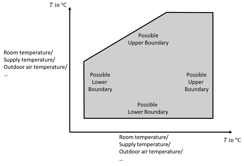
Figure 1: Possible upper and lower boundaries as well as temperature specifications in datasheets
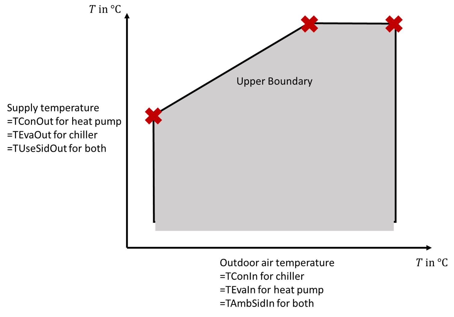
Figure 2: Example for an air-to-water heat pump or chiller. The supply temperature is the temperature leaving the device into the hydraulic circuit of the building. Red crosses indicate the point to write into the 2D table in Modelica.
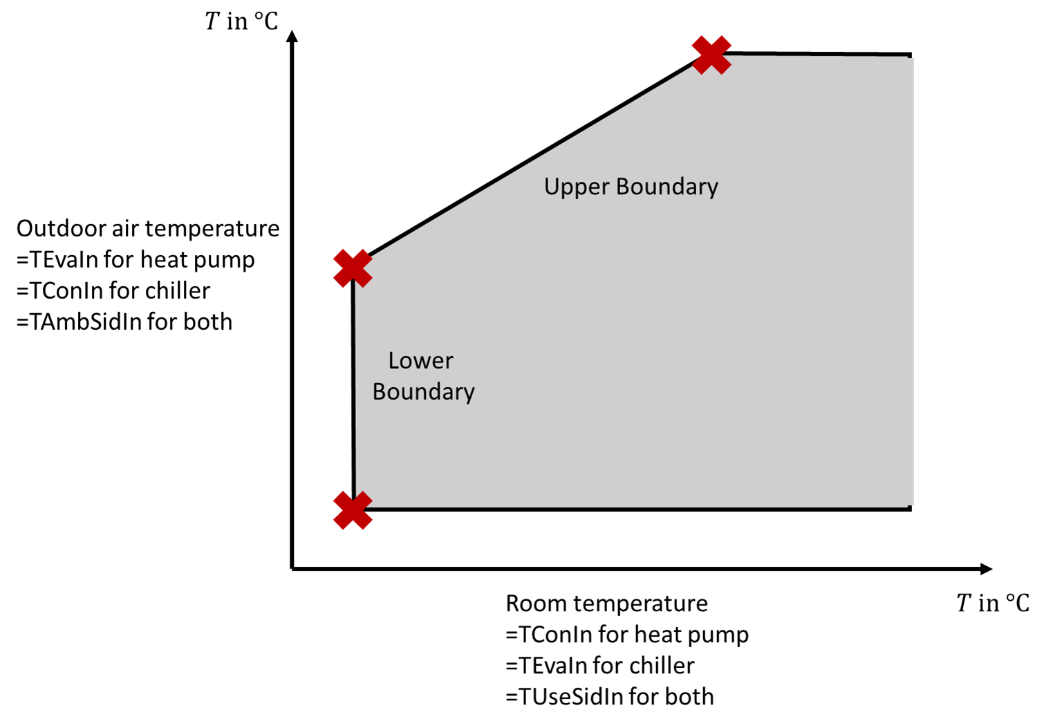
Figure 3: Example for an air-to-air heat pump or chiller. The room temperature acts as an inflow to the device. Red crosses indicate the point to write into the 2D table in Modelica.
Parameters
| Type | Name | Default | Description |
|---|---|---|---|
| Modelica.Units.SI.Temperature[:,2] | tabUppHea | Upper boundary for heating with second column as useful temperature side | |
| Modelica.Units.SI.Temperature[:,2] | tabLowCoo | Lower boundary for cooling with second column as useful temperature side | |
| Modelica.Units.SI.TemperatureDifference | dTHys | 5 | Temperature deadband in the operational envelope |
| Operational Envelope | |||
| Boolean | use_TConOutHea | true | if true, use condenser outlet temperature for operational envelope in heating mode, otherwise use inlet |
| Boolean | use_TEvaOutHea | false | if true, use evaporator outlet temperature for operational envelope in heating mode, otherwise use inlet |
| Boolean | use_TConOutCoo | false | if true, use useful side outlet temperature for operational envelope in cooling mode, otherwise use inlet |
| Boolean | use_TEvaOutCoo | true | if true, use evaporator outlet temperature for operational envelope in cooling mode, otherwise use inlet |
Connectors
| Type | Name | Default | Description |
|---|---|---|---|
| Buildings.Fluid.HeatPumps.ModularReversible.BaseClasses.RefrigerantMachineControlBus | sigBus (from PartialSafety) | Bus-connector for the heat pump | |
| Modelica.Blocks.Interfaces.IntegerOutput | err (from PartialSafetyWithCounter) | Integer for displaying number of errors during simulation | |
| Modelica.Blocks.Interfaces.BooleanInput | onOffSet (from PartialSafetyWithCounter) | Device is set to turn on | |
| Modelica.Blocks.Interfaces.BooleanOutput | canOpe (from PartialSafetyWithCounter) | True if device can operate |
Components
| Type | Name | Default | Description |
|---|---|---|---|
| Modelica.Blocks.MathInteger.TriggeredAdd | disErr (from PartialSafetyWithCounter) | Used to show if the error was triggered | |
| Modelica.Blocks.Logical.Not | notVal (from PartialSafetyWithCounter) | =true indicates a error | |
| Modelica.Blocks.Sources.IntegerConstant | intConOne (from PartialSafetyWithCounter) | Used for display of current error | |
| Modelica.Blocks.Routing.BooleanPassThrough | booPasThr (from PartialSafetyWithCounter) | Used to keep the connection to the counter | |
| Modelica.Blocks.Logical.And | errAndSetOn (from PartialSafetyWithCounter) | Error occured and the device should be on | |
| Buildings.Fluid.HeatPumps.ModularReversible.Controls.Safety.BaseClasses.BoundaryMap | bouMapHea | Operational boundary map for heating operation | |
| Buildings.Fluid.HeatPumps.ModularReversible.Controls.Safety.BaseClasses.BoundaryMap | bouMapCoo | Operational boundary map for cooling operation | |
| Modelica.Blocks.Logical.LogicalSwitch | swiHeaCoo | Switch between heating and cooling envelope |
Revisions
-
May 27, 2025 by Fabian Wuellhorst:
Make safety checks parallel (see issue IBPSA #2015) -
May 26, 2025 by Fabian Wuellhorst and Michael Wetter:
Increase error counter only when device should turn on (see issue IBPSA #2011) -
May 22, 2025, by Michael Wetter:
Revised comment.
This is for href="https://github.com/ibpsa/modelica-ibpsa/issues/2007">IBPSA #2007. -
November 26, 2018 by Fabian Wuellhorst:
First implementation (see issue AixLib #577)