
blockTableData2DLoadDep

Extends from Modelica.Blocks.Icons.Block (Basic graphical layout of input/output block).
Information
This block implements two core features for some chiller and heat pump models within Buildings.Fluid.HeatPumps.ModularReversible and Buildings.Fluid.Chillers.ModularReversible.
-
Ideal controls: The heating or cooling load is calculated based on the block
inputs. The block returns the required part load ratio
PLRto meet the load, within system capacity.1 -
Capacity and power calculation: The capacity and power are interpolated
from user-provided data along the load side fluid temperature,
the ambient side fluid temperature
and the part load ratio
yMeaprovided as input.2
1 The part load ratio is defined as the ratio of the actual heating
(or cooling) heat flow rate to the maximum capacity of the heat pump (or chiller)
at the given load-side and ambient-side fluid temperatures.
It is dimensionless and bounded by 0 and max(PLRSup), where
the upper bound is typically equal to 1 (unless there are some
capacity margins at design conditions that need to be accounted for).
In this block, the part load ratio is used as a proxy variable
for the actual capacity modulation observable.
For systems with VFDs, this is the compressor speed.
For systems with on/off compressors, this is the capacity of the enabled
compressors divided by the total capacity.
When meeting the load by cycling on and off a single compressor,
this is the time fraction the compressor is enabled.
In all cases, the algorithm assumes continuous operation and only approximates
the performance on a time average.
Finally, note that while the part load ratio is used for generalization purposes,
either the part load ratio or the actual capacity modulation observable
(e.g., the normalized compressor speed) may be used to map the performance data.
The only requirement is that this variable be normalized, as the algorithm assumes
it equals 1 at design (selection) conditions.
2 The reason why the part load ratio is both calculated (PLR)
and exposed as an input (yMea) is to allow for modeling internal safeties
that can limit operation.
If no safeties are modeled, a direct feedback of PLR to
yMea can be used.
Capacity and power calculation
When the machine is enabled (input signal on is true)
the capacity and power are calculated by partitioning the PLR values
into three domains, as illustrated in Figure 1.
- Normal capacity modulation
This domain corresponds to the capacity range where the machine adapts to the load without false loading or cycling on and off the last operating compressor. Depending on the technology, this is achieved for example by modulating the compressor speed, throttling the inlet guide vanes or staging a varying number of compressors. In this domain, both the machine PLR and the compressor PLR vary. The capacity and power are linearly interpolated based on the performance data provided in an external file, which syntax is specified in the following section. The interpolation is carried out along three variables: the load-side fluid temperature, the ambient-side fluid temperature and the part load ratio. Note that no extrapolation is performed. The capacity and power are limited by the minimum or maximum values provided in the performance data file. - Compressor false loading
This domain corresponds to the capacity range where the machine adapts to the load by false loading the compressor. For a chiller, this is achieved by bypassing hot gas directly to the evaporator. In this domain, the machine PLR varies while the compressor PLR stays roughly the same. The input power is considered equal to the interpolated value atTLoa,TAmb,min(PLRSup). This domain may not exist if the parameterPLRCyc_minis equal tomin(PLRSup), which is the default setting. - Last operating compressor cycling
This domain corresponds to the capacity range where the last operating compressor cycles on and off. In this domain, the capacity is linearly interpolated between0and the value atTLoa,TAmb,min(PLRSup), while the power is linearly interpolated betweenP_minand the value atTLoa,TAmb,min(PLRSup), whereP_mincorresponds to the remaining power when the machine is enabled and all compressors are disabled.
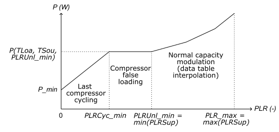
Figure 1. Input power as a function of the part load ratio.
Performance data file
The performance data are read from an external ASCII file that must meet the requirements specified in the documentation of Modelica.Blocks.Tables.CombiTable2Ds.
In addition, this file must contain at least two 2D-tables that provide the maximum
heating (resp. minimum cooling) heat flow rate and the input power
of the heat pump (resp. chiller) at 100 %
PLR.
Each row of these tables corresponds to a value of the load-side
fluid temperature, each column corresponds to a value of the
ambient-side fluid temperature.
This could be either the leaving temperature if use_T*OutForTab
is true, or the entering temperature if use_T*OutForTab
is false.
The load and ambient temperatures must cover the whole operating domain,
knowing that the model only performs interpolation and no extrapolation
of the capacity and power along these variables.
The table providing the capacity values must be named q@X.XX
where X.XX is the PLR value formatted with exactly
2 decimal places ("%.2f").
Similarly, the table providing the power values must be named
p@X.XX.
Here is an example of chiller data ("-----" is not part of the file content):
-----------------------------------------------------
#1
double q@1.00(5,5)                    # Cooling heat flow rate at 100 % PLR
0 292.0 297.4 302.8 308.2             # CW temperatures as column headers
280.4 -493241 -555900 -495611 -312372 # Each row provides the capacity at a given CHW temperature
282.2 -470560 -578165 -562822 -424529
284.1 -418413 -573462 -605561 -514711
285.9 -342290 -542284 -619329 -573426
double p@1.00(5, 5)                   # Input power at 100 % PLR
0 292.0 297.4 302.8 308.2             # CW temperatures as column headers
280.4 60430 80413 80830 55530         # Each row provides the input power at a given CHW temperature
282.2 54399 80278 89151 73950
284.1 45251 76017 92822 87633
285.9 34546 68567 91833 95401
-----------------------------------------------------
In addition, for machines that have capacity modulation other than
cycling on and off a single compressor, the whole range of normal
capacity modulation must be covered by providing similar 2D-tables
at different PLR values.
The lowest PLR value will be considered as the minimum PLR value
before false loading the compressor.
If the machine has no hot gas bypass (PLRCyc_min = min(PLRSup))
this will correspond to the minimum PLR value before cycling the
last operating compressor.
All the PLR values used in the performance data file must be specified
in the array parameter PLRSup[:].
Compressor cycling
Compressor cycling is not explicitly modeled.
Instead, the model assumes continuous operation from 0 to max(PLRSup).
The only effect of cycling taken into account is the impact of the remaining power
P_min when the machine is enabled and the last operating
compressor is cycled off.
Studies on chillers and heat pumps show that this is the main driver of
efficiency loss due to cycling (Rivière, 2004).
When a compressor is staged on, energy losses occur due to the overcoming of the
refrigerant pressure equalization and the heat exchanger temperature conditioning.
However, a large part of these losses is recovered when staging off the compressor,
unless the machine is disconnected from the load when compressors are disabled.
This disconnection does not happen when staging multiple compressors,
and the research shows no significant performance degradation when a
chiller cycles between different stages without completely shutting down.
And even when disabling the last operating compressor, most plant
controls require continuous operation of the primary pumps when
the chillers or heat pumps are enabled.
The European Standard for performance rating of chillers and heat pumps
at part load conditions (CEN, 2022) states that the performance degradation due to
the pressure equalization effect when the unit restarts can be considered
as negligible for hydronic systems.
The only effect that will impact the coefficient of performance
when cycling is the remaining power input when the compressor is switching off.
If this remaining power is not measured, the Standard prescribes a default
value of 10 % of the effective power input measured
during continuous operation at part load.
Heat recovery chillers
Heat recovery chillers can be modeled with this block. In this case, the same chiller performance data file is used for both cooling and heating operation. The model assumes that all dissipated heat from the compressor is recovered by the refrigerant. This assumption enables computing the heating capacity as the sum of the cooling capacity and the input power.
When configured to represent a heat recovery chiller, this block uses an
additional input connector coo which must be true when
cooling mode is enabled, and false when heating mode is enabled.
The load side input variables must externally be connected to the
evaporator side variables in cooling mode, and to the condenser side
variables in heating mode.
The output connector Q_flow is always the
cooling heat flow rate, whatever the operating mode.
The heating heat flow rate in heating mode can be computed
externally as P-Q_flow.
Ideal controls
The block implements ideal controls by solving for the part load ratio required to meet the load (more precisely the minimum between the load and the actual capacity for the current load and ambient temperatures). This is done by interpolating the PLR values along the heat flow rate values for a given load.
The load is calculated based on the load side variables and the temperature
setpoint provided as inputs. The setpoint either represents a leaving (supply)
temperature setpoint if use_TLoaLvgForCtl is true (default setting)
or the entering (return) temperature if use_TLoaLvgForCtl is false.
The required PLR value is returned as an output while the actual heat flow rate
and power are calculated using the PLR value yMea provided as input,
which allows limiting the required PLR to account for equipment internal safeties.
References
- CEN, 2022. European Standard EN 14825:2022 E. Air conditioners, liquid chilling packages and heat pumps, with electrically driven compressors, for space heating and cooling, commercial and process cooling - Testing and rating at part load conditions and calculation of seasonal performance.
- Rivière, P. (2004). Performances saisonnières des groupes de production d’eau glaçée [Seasonal performance of liquid chillers]. École Nationale Supérieure des Mines de Paris. [In French]. https://pastel.hal.science/pastel-00001483
Parameters
| Type | Name | Default | Description |
|---|---|---|---|
| TypeOfSystem | typ | ||
| Boolean | use_TLoaLvgForCtl | true | Set to true for leaving temperature control, false for entering temperature control |
| Boolean | use_TEvaOutForTab | =true to use evaporator outlet temperature for table data, false for inlet | |
| Boolean | use_TConOutForTab | =true to use condenser outlet temperature for table data, false for inlet | |
| Real | scaFac | 1 | Scaling factor for interpolated heat flow rate and power |
| Modelica.Units.SI.DimensionlessRatio[:] | PLRSup | PLR values at which heat flow rate and power data are provided | |
| Modelica.Units.SI.DimensionlessRatio | PLRUnl_min | min(PLRSup) | Minimum PLR before false loading the compressor |
| Modelica.Units.SI.DimensionlessRatio | PLRCyc_min | min(PLRSup) | Minimum PLR before cycling off the last compressor |
| Modelica.Units.SI.Power | P_min | 0 | Minimum power when system is enabled with compressor cycled off |
| Integer | nPLR | size(PLRSup, 1) | Number of PLR support points |
| String | fileName | File where performance data are stored | |
| Modelica.Blocks.Types.Smoothness | smoothness | Modelica.Blocks.Types.Smoothness.LinearSegments | Smoothness of table interpolation |
| Modelica.Blocks.Types.Extrapolation | extrapolation | Modelica.Blocks.Types.Extrapolation.HoldLastPoint | Extrapolation of data outside the definition range |
| Modelica.Units.SI.Power[nPLR] | PInt_nominal | Power interpolated at nominal conditions, at each PLR – Unscaled | |
| Modelica.Units.SI.HeatFlowRate[nPLR] | QInt_flow_nominal | Heat flow rate interpolated at nominal conditions, at each PLR – Unscaled | |
| Modelica.Units.SI.Power | P_nominal | Modelica.Math.Vectors.interpolate(PLRSor, PInt_nominal, 1) | Power interpolated at nominal conditions, at PLR=1 – Unscaled |
| Modelica.Units.SI.HeatFlowRate | Q_flow_nominal | Modelica.Math.Vectors.interpolate(PLRSor, QInt_flow_nominal, 1) | Heat flow rate interpolated at nominal conditions, at PLR=1 – Unscaled |
| Advanced | |||
| String[nPLR] | tabNamQ | {"q@" + String(p, format = ".2f") for p in PLRSor} | Table names with heat flow rate data |
| String[nPLR] | tabNamP | {"p@" + String(p, format = ".2f") for p in PLRSor} | Table names with power data |
| Nominal condition | |||
| Modelica.Units.SI.Temperature | TLoa_nominal | Load side fluid temperature — Entering or leaving depending on use_T*OutForTab | |
| Modelica.Units.SI.Temperature | TAmb_nominal | Ambient side fluid temperature — Entering or leaving depending on use_T*OutForTab | |
Connectors
| Type | Name | Default | Description |
|---|---|---|---|
| Buildings.Controls.OBC.CDL.Interfaces.BooleanInput | on | Set to true to enable compressor, or false to disable compressor | |
| Buildings.Controls.OBC.CDL.Interfaces.BooleanInput | coo | Switchover signal: true for cooling, false for heating | |
| Buildings.Controls.OBC.CDL.Interfaces.RealInput | TLoaEnt | Entering fluid temperature on load side | |
| Buildings.Controls.OBC.CDL.Interfaces.RealInput | TAmbEnt | Entering fluid temperature on ambient side | |
| Buildings.Controls.OBC.CDL.Interfaces.RealInput | TSet | Temperature setpoint | |
| Buildings.Controls.OBC.CDL.Interfaces.RealInput | TLoaLvg | Leaving fluid temperature on load side | |
| Buildings.Controls.OBC.CDL.Interfaces.RealInput | mLoa_flow | Fluid mass flow rate on load side | |
| Buildings.Controls.OBC.CDL.Interfaces.RealOutput | P | Input power | |
| Buildings.Controls.OBC.CDL.Interfaces.RealOutput | PLR | Compressor part load ratio to meet the load (within capacity) | |
| Buildings.Controls.OBC.CDL.Interfaces.RealOutput | Q_flow | Heat flow rate | |
| Buildings.Controls.OBC.CDL.Interfaces.RealInput | TAmbLvg | Leaving fluid temperature on ambient side | |
| Buildings.Controls.OBC.CDL.Interfaces.RealInput | yMea | Capacity limiting signal yielded by internal safety logic | |
| Buildings.Controls.OBC.CDL.Interfaces.RealInput | cpLoa | Specific heat capacity of fluid on load side |
Contents
| Name | Description |
|---|---|
| TypeOfSystem |
Revisions
-
March 21, 2025, by Antoine Gautier:
First implementation.