
modelInjectionTwoWayConstant
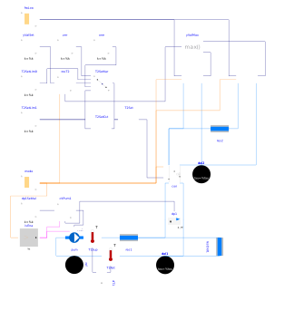
Extends from Fluid.HydronicConfigurations.ActiveNetworks.Examples.BaseClasses.PartialInjectionTwoWay (Partial model of primary variable circuit serving an inversion circuit with two-way valve).
Information
This model represents a heating system where the configuration Buildings.Fluid.HydronicConfigurations.ActiveNetworks.InjectionTwoWay serves as the interface between a variable flow primary circuit and a constant flow secondary circuit. Two identical terminal units are served by the secondary circuit. Each terminal unit has its own hourly load profile. The main assumptions are enumerated below.
- The design conditions are defined without considering any load diversity.
- Each circuit is balanced at design conditions.
- The pump dissipated heat is not added to the fluid.
-
The consumer circuit has either a constant (supply or return)
temperature set point if
have_resT2=falseor a temperature reset ifhave_resT2=true. The reset logic is based on the terminal valve opening, with the most open valve being kept 90% open.
Without temperature reset (have_resT2=false),
the primary flow variation with the load is not optimal (see plot #8):
for a load fraction of 30% the normalized primary flow rate
is about 60%.
The flow reduction is enhanced when using a reset based on the maximum
valve demand:
for a load fraction of 30% the normalized primary flow rate
is now close to 30%.
(Also note the setting of the controller resT2 which ensures
a reset at design value when the control loop is enabled).
The flow reduction is further enhanced when using a control based on the
return temperature
(have_resT2 = false and
con(typVar=Types.ControlVariable.ReturnTemperature)):
the normalized primary flow rate varies close to linearly with the
load fraction.
This explains why this control strategy is often adopted
as it brings a good flow rate variation with the load at a
first cost lower than the previous reset option based on the valve demand.
However, it also brings some additional constraints on the sizing of
the terminal units.
The load diversity must indeed be accounted for.
When tracking the return temperature of a constant flow consumer circuit,
the supply temperature will vary with the aggregated load.
In our example, the actual value of the secondary supply temperature
is lower than its design value at partial load, which yields unmet loads
(see plot #4). The terminal units should be sized accordingly,
based on the lowest possible ΔT when one terminal unit may still be at peak load.
Additional caveats speak against the use of return temperature control
with this hydronic configuration in the case of variable flow consumer circuits,
see
Buildings.Fluid.HydronicConfigurations.ActiveNetworks.Examples.InjectionTwoWayVariableReturn.
Parameters
| Type | Name | Default | Description |
|---|---|---|---|
| Buildings.Fluid.HydronicConfigurations.Types.Control | typ (from PartialActivePrimary) | Buildings.Fluid.HydronicConfigurations.Types.Control.Heating | Load type |
| Integer | nTer (from PartialActivePrimary) | 2 | Number of terminal units |
| Real | kSizPum (from PartialActivePrimary) | 1.0 | Pump oversizing coefficient |
| Modelica.Units.SI.Pressure | p_min (from PartialActivePrimary) | 200000 | Circuit minimum pressure |
| Modelica.Units.SI.Temperature | TLiqEnt_nominal (from PartialActivePrimary) | if typ == Buildings.Fluid.HydronicConfigurations.Types.Control.Heating then 60 + 273.15 else 7 + 273.15 | Liquid entering temperature at design conditions |
| Modelica.Units.SI.Temperature | TLiqLvg_nominal (from PartialActivePrimary) | TLiqEnt_nominal + (if typ == Buildings.Fluid.HydronicConfigurations.Types.Control.Heating then -10 else +5) | Liquid leaving temperature at design conditions |
| Modelica.Units.SI.Temperature | TLiqEntChg_nominal (from PartialActivePrimary) | 60 + 273.15 | Liquid entering temperature in change-over mode |
| Modelica.Units.SI.Temperature | TLiqSup_nominal (from PartialActivePrimary) | TLiqEnt_nominal | Liquid primary supply temperature at design conditions |
| Modelica.Units.SI.Temperature | TLiqSupChg_nominal (from PartialActivePrimary) | TLiqEntChg_nominal | Liquid primary supply temperature in change-over mode |
| Nominal condition | |||
| Modelica.Units.SI.MassFlowRate | mTer_flow_nominal (from PartialActivePrimary) | 1 | Terminal unit mass flow rate at design conditions |
| Modelica.Units.SI.MassFlowRate | m1_flow_nominal (from PartialActivePrimary) | m2_flow_nominal | Mass flow rate in primary branch at design conditions |
| Modelica.Units.SI.MassFlowRate | m2_flow_nominal (from PartialActivePrimary) | nTer*mTer_flow_nominal | Mass flow rate in consumer circuit at design conditions |
| Modelica.Units.SI.PressureDifference | dpTer_nominal (from PartialActivePrimary) | 3E4 | Terminal unit pressure drop at design conditions |
| Modelica.Units.SI.PressureDifference | dpPip_nominal (from PartialActivePrimary) | 0.5E4 | Pipe section pressure drop at design conditions |
| Modelica.Units.SI.PressureDifference | dpPum_nominal (from PartialActivePrimary) | Pump head at design conditions | |
| Modelica.Units.SI.MassFlowRate | mPum_flow_nominal (from PartialActivePrimary) | m1_flow_nominal | Primary pump mass flow rate at design conditions |
| Modelica.Units.SI.PressureDifference | dp2_nominal (from PartialInjectionTwoWay) | Consumer circuit pressure differential at design conditions | |
| Modelica.Units.SI.Temperature | T2Set_nominal | if con.typVar == Buildings.Fluid.HydronicConfigurations.Types.ControlVariable.SupplyTemperature then TLiqEnt_nominal else TLiqLvg_nominal | Consumer circuit design temperature set point |
| Modelica.Units.SI.Temperature | TAirEnt_nominal | 293.15 | Air entering temperature at design conditions |
| Modelica.Units.SI.MassFraction | phiAirEnt_nominal | 0.5 | Air entering relative humidity at design conditions |
| Dynamics › Conservation equations | |||
| Modelica.Fluid.Types.Dynamics | energyDynamics (from PartialActivePrimary) | Modelica.Fluid.Types.Dynamics.FixedInitial | Type of energy balance: dynamic (3 initialization options) or steady state |
| Configuration | |||
| Boolean | is_bal (from PartialInjectionTwoWay) | false | Set to true for balanced primary branch |
| Boolean | have_resT2 | false | Set to true for consumer circuit temperature reset, false for constant set point |
| Controls | |||
| Modelica.Units.SI.PressureDifference | dp1Set (from PartialInjectionTwoWay) | 1e4 | Pressure differential set point |
Components
Revisions
-
June 30, 2022, by Antoine Gautier:
First implementation.