
modelThrottleOpenLoop
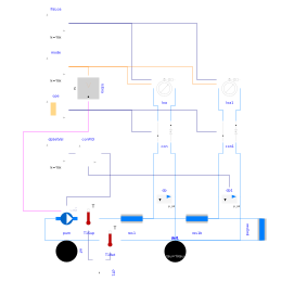
Extends from BaseClasses.PartialActivePrimary (Partial model of active primary network).
Information
This model represents a heating system where the configuration Buildings.Fluid.HydronicConfigurations.ActiveNetworks.Throttle is used to modulate the heat flow rate transmitted to a constant load. Two identical secondary circuits are connected to a primary circuit with a variable speed pump. The pump speed is modulated to track a constant pressure differential at the boundaries of the remote circuit. The main assumptions are enumerated below.
- The model is configured in steady-state.
-
The design conditions at
time = 0are defined without considering any load diversity. -
Each consumer circuit is balanced at design conditions if the parameter
is_balis set totrue. - The pipe pressure drop between the two consumer circuits is voluntarily high to showcase typical balancing issues encountered in large distribution systems.
When simulated with the default parameter values, this example shows the following points.
-
When the consumer circuits are unbalanced (
is_bal=false), the overflow in the circuit that is the closest to the pump is about 20% (see plot #2). However, the corresponding flow shortage in the remote circuit is limited to about 2% due to equivalent flow resistance seen by the pump that is lower than design, shifting the operating point towards higher flow rates (see plot #5). The impact on the heat flow rate transferred to the load (see plot #4) is of an even lower amplitude (1%) due to the emission characteristic of the terminal unit. -
When the consumer circuits are balanced (
is_bal=true), the flow shortage in the circuit that is the closest to the pump is more significant, nearing 20% when the remote circuit has no demand (see plot #2). The impact on the heat flow rate transferred to the load (see plot #4) becomes tangible (8%) while still being not critical.
Sensitivity analysis
Those observations are confirmed by a sensitivity study to the following parameters.
- Ratio of the terminal unit pressure drop to the pump head at design conditions (refer to the schematic in the documentation of Buildings.Fluid.HydronicConfigurations.ActiveNetworks.Throttle for the nomenclature): ψ = Δp2 / Δppump varying from 0.1 to 0.4
- Ratio of the control valve authority: β = ΔpA-B / Δp1 varying from 0.1 to 0.7
-
Balanced circuit:
is_balswitched fromfalsetotrue
Valve mass flow rate
When the circuits are not balanced, Figure 1 shows that the overflow through the terminal unit closest to the pump may reach 100% of the design flow rate for low values of ψ and β. However, the concomitant flow shortage in the other terminal unit with a valve fully open is limited to about 40% and the coil capacity is reduced by less than 20% (see Figure 2). A good valve authority (higher than 0.5) does not help improving the situation.
When the circuits are balanced, the overflow is eliminated but the flow shortage is even higher (reaching 60%) and becomes critical with respect to the coil capacity that gets reduced by nearly 40%. A good valve authority (higher than 0.5) slightly helps improving the situation, which remains worse than in the case of unbalanced circuits though.
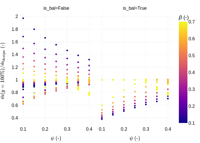
Figure 1. Valve mass flow rate (ratio to design value) at fully open conditions
as a function of
ψ for various valve authorities β (color scale),
and a circuit either balanced (right plot) or not (left plot).
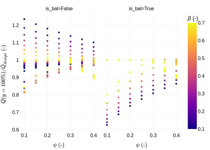
Figure 2. Heat flow rate (ratio to design value) at fully open conditions
as a function of
ψ for various valve authorities β (color scale),
and a circuit either balanced (right plot) or not (left plot).
Parameters
| Type | Name | Default | Description |
|---|---|---|---|
| Buildings.Fluid.HydronicConfigurations.Types.Control | typ (from PartialActivePrimary) | Buildings.Fluid.HydronicConfigurations.Types.Control.Heating | Load type |
| Integer | nTer (from PartialActivePrimary) | 2 | Number of terminal units |
| Real | kSizPum (from PartialActivePrimary) | 1.0 | Pump oversizing coefficient |
| Modelica.Units.SI.Pressure | p_min (from PartialActivePrimary) | 200000 | Circuit minimum pressure |
| Modelica.Units.SI.Temperature | TLiqEnt_nominal (from PartialActivePrimary) | if typ == Buildings.Fluid.HydronicConfigurations.Types.Control.Heating then 60 + 273.15 else 7 + 273.15 | Liquid entering temperature at design conditions |
| Modelica.Units.SI.Temperature | TLiqLvg_nominal (from PartialActivePrimary) | TLiqEnt_nominal + (if typ == Buildings.Fluid.HydronicConfigurations.Types.Control.Heating then -10 else +5) | Liquid leaving temperature at design conditions |
| Modelica.Units.SI.Temperature | TLiqEntChg_nominal (from PartialActivePrimary) | 60 + 273.15 | Liquid entering temperature in change-over mode |
| Modelica.Units.SI.Temperature | TLiqSup_nominal (from PartialActivePrimary) | TLiqEnt_nominal | Liquid primary supply temperature at design conditions |
| Modelica.Units.SI.Temperature | TLiqSupChg_nominal (from PartialActivePrimary) | TLiqEntChg_nominal | Liquid primary supply temperature in change-over mode |
| Modelica.Units.SI.PressureDifference | dpValve_nominal | dpTer_nominal | Control valve pressure drop at design conditions |
| Modelica.Units.SI.PressureDifference | dpValve1_nominal | dpTer_nominal | Control valve pressure drop at design conditions |
| Modelica.Units.SI.PressureDifference | dpPip1_nominal | 3E4 | Pipe section (between two circuits) pressure drop at design conditions |
| Nominal condition | |||
| Modelica.Units.SI.MassFlowRate | mTer_flow_nominal (from PartialActivePrimary) | 1 | Terminal unit mass flow rate at design conditions |
| Modelica.Units.SI.MassFlowRate | m1_flow_nominal (from PartialActivePrimary) | m2_flow_nominal | Mass flow rate in primary branch at design conditions |
| Modelica.Units.SI.MassFlowRate | m2_flow_nominal (from PartialActivePrimary) | nTer*mTer_flow_nominal | Mass flow rate in consumer circuit at design conditions |
| Modelica.Units.SI.PressureDifference | dpTer_nominal (from PartialActivePrimary) | 3E4 | Terminal unit pressure drop at design conditions |
| Modelica.Units.SI.PressureDifference | dpPip_nominal (from PartialActivePrimary) | 0.5E4 | Pipe section pressure drop at design conditions |
| Modelica.Units.SI.PressureDifference | dpPum_nominal (from PartialActivePrimary) | Pump head at design conditions | |
| Modelica.Units.SI.MassFlowRate | mPum_flow_nominal (from PartialActivePrimary) | m1_flow_nominal | Primary pump mass flow rate at design conditions |
| Dynamics › Conservation equations | |||
| Modelica.Fluid.Types.Dynamics | energyDynamics (from PartialActivePrimary) | Modelica.Fluid.Types.Dynamics.FixedInitial | Type of energy balance: dynamic (3 initialization options) or steady state |
| Configuration | |||
| Boolean | is_bal | false | Set to true for balanced primary branch |
| Buildings.Fluid.HydronicConfigurations.Types.ValveCharacteristic | typCha | Buildings.Fluid.HydronicConfigurations.Types.ValveCharacteristic.EqualPercentage | Control valve characteristic |
| Controls | |||
| Modelica.Units.SI.PressureDifference | dp1Set | dpValve1_nominal + dpTer_nominal | Pressure differential set point |
Components
Revisions
-
June 30, 2022, by Antoine Gautier:
First implementation.