
modelSingleMixingOpenLoop
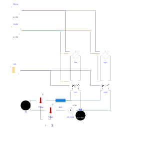
Extends from BaseClasses.PartialPassivePrimary (Partial model of passive primary network).
Information
This model illustrates the disturbance caused on the three-way valve
operation by an induced negative pressure differential at the
circuit boundaries.
Two consumer circuits are connected to a primary loop by means of
Buildings.Fluid.HydronicConfigurations.PassiveNetworks.SingleMixing.
The primary loop is configured with a flow resistance that
generates a negative pressure differential at the boundaries of the
consumer circuits
(representing for instance a boiler with a high pressure drop
and no minimum flow requirement).
Each consumer circuit is equipped with a circulation pump
that is sized to cover the primary pressure differential.
When the parameter is_bal is false
no bypass balancing valve is considered.
When this parameter is true a bypass balancing
valve is considered with the same design pressure drop
as the one in the primary loop.
The pump design head remains unchanged whatever the value
of the parameter is_bal.
The model is configured in steady-state with open loop control.
The load on each consumer circuit is constant.
The control valve of the first circuit is modulated
from fully open to fully closed position while the
control valve of the remote circuit is kept fully open.
When the bypass is not balanced, the flow reverses in the primary branch when the valve opening is below 20% which means that the load cannot be served any more.
When the bypass is balanced, no flow reversal occurs and the mixing function of the three-way valve is preserved over its whole opening range.
Note that the setting of this model represents an oversized control valve with a low authority β = 0.14. Setting a higher valve design pressure drop to reach an authority close to 0.5 alleviates the risk of primary flow reversal and reduces the need for a bypass balancing valve.
Parameters
| Type | Name | Default | Description |
|---|---|---|---|
| Buildings.Fluid.HydronicConfigurations.Types.Control | typ (from PartialPassivePrimary) | Load type | |
| Integer | nTer (from PartialPassivePrimary) | 2 | Number of terminal units |
| Modelica.Units.SI.Pressure | p_min (from PartialPassivePrimary) | 200000 | Circuit minimum pressure |
| Modelica.Units.SI.Temperature | TLiqEnt_nominal (from PartialPassivePrimary) | if typ == Buildings.Fluid.HydronicConfigurations.Types.Control.Heating then 60 + 273.15 else 7 + 273.15 | Liquid entering temperature at design conditions |
| Modelica.Units.SI.Temperature | TLiqLvg_nominal (from PartialPassivePrimary) | TLiqEnt_nominal + (if typ == Buildings.Fluid.HydronicConfigurations.Types.Control.Heating then -10 else +5) | Liquid leaving temperature at design conditions |
| Modelica.Units.SI.Temperature | TLiqEntChg_nominal (from PartialPassivePrimary) | 60 + 273.15 | Liquid entering temperature in change-over mode |
| Modelica.Units.SI.Temperature | TLiqSup_nominal (from PartialPassivePrimary) | TLiqEnt_nominal | Liquid primary supply temperature at design conditions |
| Modelica.Units.SI.Temperature | TLiqSupChg_nominal (from PartialPassivePrimary) | TLiqEntChg_nominal | Liquid primary supply temperature in change-over mode |
| Modelica.Units.SI.PressureDifference | dpValve_nominal | 5e3 | Control valve pressure drop at design conditions |
| Nominal condition | |||
| Modelica.Units.SI.MassFlowRate | mTer_flow_nominal (from PartialPassivePrimary) | 1 | Terminal unit mass flow rate at design conditions |
| Modelica.Units.SI.MassFlowRate | m1_flow_nominal (from PartialPassivePrimary) | nTer*mTer_flow_nominal | Mass flow rate in primary circuit at design conditions |
| Modelica.Units.SI.PressureDifference | dpTer_nominal (from PartialPassivePrimary) | 3E4 | Terminal unit pressure drop at design conditions |
| Modelica.Units.SI.PressureDifference | dpPip_nominal (from PartialPassivePrimary) | 0.5E4 | Pipe section pressure drop at design conditions |
| Dynamics › Conservation equations | |||
| Modelica.Fluid.Types.Dynamics | energyDynamics (from PartialPassivePrimary) | Modelica.Fluid.Types.Dynamics.FixedInitial | Type of energy balance: dynamic (3 initialization options) or steady state |
| Configuration | |||
| Boolean | is_bal | false | Set to true for balanced bypass branch |
Components
Revisions
-
June 30, 2022, by Antoine Gautier:
First implementation.